DSP56303AG100 Freescale Semiconductor, DSP56303AG100 Datasheet - Page 25
DSP56303AG100
Manufacturer Part Number
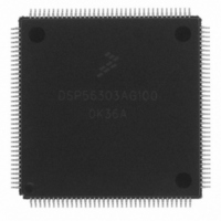
DSP56303AG100
Description
IC DSP 24BIT 100MHZ 144-LQFP
Manufacturer
Freescale Semiconductor
Series
DSP563xxr
Type
Fixed Pointr
Datasheet
1.DSP56303AG100.pdf
(108 pages)
Specifications of DSP56303AG100
Interface
Host Interface, SSI, SCI
Clock Rate
100MHz
Non-volatile Memory
ROM (576 B)
On-chip Ram
24kB
Voltage - I/o
3.30V
Voltage - Core
3.30V
Operating Temperature
-40°C ~ 100°C
Mounting Type
Surface Mount
Package / Case
144-LQFP
Package
144LQFP
Maximum Speed
100 MHz
Ram Size
24 KB
Device Million Instructions Per Second
100 MIPS
Lead Free Status / RoHS Status
Lead free / RoHS Compliant
Available stocks
Company
Part Number
Manufacturer
Quantity
Price
Company:

Part Number:
DSP56303AG100
Manufacturer:
Freescale Semiconductor
Quantity:
10 000
Company:
Part Number:
DSP56303AG100B1
Manufacturer:
Freescale Semiconductor
Quantity:
10 000
Company:
Part Number:
DSP56303AG100R2
Manufacturer:
Freescale Semiconductor
Quantity:
10 000


2.5.3
Freescale Semiconductor
Notes:
Voltage Controlled Oscillator (VCO) frequency when PLL enabled
(MF × E
PLL external capacitor (PCAP pin to V
•
•
Note:
No.
1
2
3
4
5
6
7
@ MF ≤ 4
@ MF > 4
Frequency of EXTAL (EXTAL Pin Frequency)
The rise and fall time of this external clock should be 3 ns maximum.
EXTAL input high
•
•
EXTAL input low
•
•
EXTAL cycle time
•
•
Internal clock change from EXTAL fall with PLL disabled
a.Internal clock rising edge from EXTAL rising edge with PLL enabled (MF = 1 or 2 or
4, PDF = 1, Ef > 15 MHz)
b. Internal clock falling edge from EXTAL falling edge with PLL enabled (MF ≤ 4, PDF ≠
1,
Instruction cycle time = I
(see Table 2-4) (46.7%–53.3% duty cycle)
•
•
f
× 2/PDF)
1.
2.
3.
4.
5.
6.
C
listed above.
With PLL disabled (46.7%–53.3% duty cycle
With PLL enabled (42.5%–57.5% duty cycle
With PLL disabled (46.7%–53.3% duty cycle
With PLL enabled (42.5%–57.5% duty cycle
With PLL disabled
With PLL enabled
With PLL disabled
With PLL enabled
PCAP
Ef / PDF > 15 MHz)
Phase Lock Loop (PLL) Characteristics
Measured at 50 percent of the input transition.
The maximum value for PLL enabled is given for minimum VCO frequency (see Table 2-4) and maximum MF.
Periodically sampled and not 100 percent tested.
The maximum value for PLL enabled is given for minimum VCO frequency and maximum DF.
The skew is not guaranteed for any other MF value.
The indicated duty cycle is for the specified maximum frequency for which a part is rated. The minimum clock high or low time
required for correction operation, however, remains the same at lower operating frequencies; therefore, when a lower clock
frequency is used, the signal symmetry may vary from the specified duty cycle as long as the minimum high time and low time
requirements are met.
is the value of the PLL capacitor (connected between the PCAP pin and V
1, 2
1, 2
2
CYC
3,5
Characteristics
3,5
= T
CCP
C
4
Characteristics
) (C
PCAP
Table 2-6.
DSP56303 Technical Data, Rev. 11
1
Table 2-5.
)
6
6
6
6
)
)
)
)
PLL Characteristics
Clock Operation
(580 × MF) − 100
CCP
830 × MF
Min
) computed using the appropriate expression
30
Symbol
ET
ET
I
ET
CYC
Ef
H
C
L
100 MHz
AC Electrical Characteristics
(780 × MF) − 140
10.00 ns
10.00 ns
10.00 ns
4.67 ns
4.25 ns
4.67 ns
4.25 ns
20.0 ns
4.3 ns
0.0 ns
0.0 ns
Min
1470 × MF
0
Max
200
100 MHz
157.0 µs
157.0 µs
273.1 µs
11.0 ns
8.53 µs
1.8 ns
1.8 ns
100.0
Max
∞
∞
∞
∞
Unit
MHz
pF
pF
2-5
Related parts for DSP56303AG100
Image
Part Number
Description
Manufacturer
Datasheet
Request
R

Part Number:
Description:
DSP56303 USER�S MANUAL
Manufacturer:
FREESCALE [Freescale Semiconductor, Inc]
Datasheet:
Part Number:
Description:
DSP56303 Software Differences Between the DSP56002 and the DSP56303
Manufacturer:
Freescale Semiconductor / Motorola
Part Number:
Description:
DSP56303 Hardware Differences Between the DSP56002 and the DSP56303
Manufacturer:
Freescale Semiconductor / Motorola

Part Number:
Description:
Manufacturer:
Freescale Semiconductor, Inc
Datasheet:
Part Number:
Description:
Manufacturer:
Freescale Semiconductor, Inc
Datasheet:
Part Number:
Description:
Manufacturer:
Freescale Semiconductor, Inc
Datasheet:
Part Number:
Description:
Manufacturer:
Freescale Semiconductor, Inc
Datasheet:
Part Number:
Description:
Manufacturer:
Freescale Semiconductor, Inc
Datasheet:
Part Number:
Description:
Manufacturer:
Freescale Semiconductor, Inc
Datasheet:
Part Number:
Description:
Manufacturer:
Freescale Semiconductor, Inc
Datasheet:
Part Number:
Description:
Manufacturer:
Freescale Semiconductor, Inc
Datasheet:
Part Number:
Description:
Manufacturer:
Freescale Semiconductor, Inc
Datasheet:
Part Number:
Description:
Manufacturer:
Freescale Semiconductor, Inc
Datasheet:
Part Number:
Description:
Manufacturer:
Freescale Semiconductor, Inc
Datasheet:
Part Number:
Description:
Manufacturer:
Freescale Semiconductor, Inc
Datasheet: