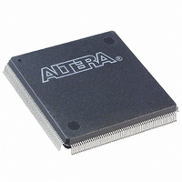
EPF10K130EQI240-2 Altera, EPF10K130EQI240-2 Datasheet - Page 97

EPF10K130EQI240-2
Manufacturer Part Number
EPF10K130EQI240-2
Description
IC FLEX 10KE FPGA 130K 240-PQFP
Manufacturer
Altera
Series
FLEX-10KE®r
Datasheet
1.EPF10K30ETC144-3.pdf
(100 pages)
Specifications of EPF10K130EQI240-2
Number Of Logic Elements/cells
6656
Number Of Labs/clbs
832
Total Ram Bits
65536
Number Of I /o
186
Number Of Gates
342000
Voltage - Supply
2.375 V ~ 2.625 V
Mounting Type
Surface Mount
Operating Temperature
-40°C ~ 100°C
Package / Case
240-MQFP, 240-PQFP
Family Name
FLEX 10KE
Number Of Usable Gates
130000
Number Of Logic Blocks/elements
6656
# Registers
186
# I/os (max)
186
Frequency (max)
333.33MHz
Process Technology
CMOS
Operating Supply Voltage (typ)
2.5V
Logic Cells
6656
Ram Bits
65536
Device System Gates
342000
Operating Supply Voltage (min)
2.375V
Operating Supply Voltage (max)
2.625V
Operating Temp Range
-40C to 100C
Operating Temperature Classification
Industrial
Mounting
Surface Mount
Pin Count
240
Package Type
PQFP
Lead Free Status / RoHS Status
Contains lead / RoHS non-compliant
Other names
544-2206
Available stocks
Company
Part Number
Manufacturer
Quantity
Price
Part Number:
EPF10K130EQI240-2
Manufacturer:
ALTERA/阿尔特拉
Quantity:
20 000
FLEX 10KE Embedded Programmable Logic Devices Data Sheet
During initialization, which occurs immediately after configuration, the
device resets registers, enables I/O pins, and begins to operate as a logic
device. The I/O pins are tri-stated during power-up, and before and
during configuration. Together, the configuration and initialization
processes are called command mode; normal device operation is called user
mode.
SRAM configuration elements allow FLEX 10KE devices to be
reconfigured in-circuit by loading new configuration data into the device.
Real-time reconfiguration is performed by forcing the device into
command mode with a device pin, loading different configuration data,
reinitializing the device, and resuming user-mode operation. The entire
reconfiguration process requires less than 85 ms and can be used to
reconfigure an entire system dynamically. In-field upgrades can be
performed by distributing new configuration files.
Before and during configuration, all I/O pins (except dedicated inputs,
clock, or configuration pins) are pulled high by a weak pull-up resistor.
Programming Files
Despite being function- and pin-compatible, FLEX 10KE devices are not
programming- or configuration file-compatible with FLEX 10K or
FLEX 10KA devices. A design therefore must be recompiled before it is
transferred from a FLEX 10K or FLEX 10KA device to an equivalent
FLEX 10KE device. This recompilation should be performed both to create
a new programming or configuration file and to check design timing in
FLEX 10KE devices, which has different timing characteristics than
FLEX 10K or FLEX 10KA devices.
FLEX 10KE devices are generally pin-compatible with equivalent
FLEX 10KA devices. In some cases, FLEX 10KE devices have fewer I/O
pins than the equivalent FLEX 10KA devices.
Table 81
shows which
FLEX 10KE devices have fewer I/O pins than equivalent FLEX 10KA
devices. However, power, ground, JTAG, and configuration pins are the
same on FLEX 10KA and FLEX 10KE devices, enabling migration from a
FLEX 10KA design to a FLEX 10KE design.
Altera Corporation
97


