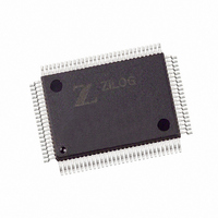
Z8018110FEC Zilog, Z8018110FEC Datasheet - Page 13

Z8018110FEC
Manufacturer Part Number
Z8018110FEC
Description
IC 10MHZ ACCESS CTRL 100-QFP
Manufacturer
Zilog
Datasheet
1.Z8018110FEG.pdf
(74 pages)
Specifications of Z8018110FEC
Processor Type
Z180
Features
Smart Access Controller SAC™
Speed
10MHz
Voltage
5V
Mounting Type
Surface Mount
Package / Case
100-QFP
Lead Free Status / RoHS Status
Contains lead / RoHS non-compliant
Available stocks
Company
Part Number
Manufacturer
Quantity
Price
Zilog
Z181 MPU
This unit provides all the capabilities and pins of the Zilog
Z180 MPU. Figure 3 shows the Z181 MPU block diagram.
This allows 100% software compatibility with existing Z180
(and Z80) software. Note that the on-chip I/O address
should not be relocated to the I/O address (from 0C0h to
0FFh) to avoid address conflicts. The following is an
overview of the major functional units of the Z181.
Z181 CPU
The Z181 CPU has 100% software compatibility with the
Z80 CPU. In addition, the Z181 CPU has the following
features:
Faster execution speed. The Z181 CPU is “fine tuned”
making execution speed, on average, 10% to 20% faster
than the Z80 CPU.
Enhanced DRAM Refresh Circuit. Z181 CPU’s DRAM
refresh circuit does periodic refresh and generates an
8-bit refresh address. It can be disabled or the refresh
period adjusted, through software control.
Enhanced Instruction Set. The Z181 CPU has seven
additional instructions to those of the Z80 CPU which
include the MLT (Multiply) instruction.
HALT and Low Power Modes of Operation. The Z181
CPU has HALT and low power modes of operation, which
are ideal for the applications requiring low power con-
sumption like battery operated portable terminals.
System Stop Mode. When the Z181 SAC is in SYSTEM
STOP mode, it is only the Z181 MPU which is in STOP
mode. The on-chip CTC and SCC continue their normal
operation.
Instruction Set. The instruction set of the Z181 CPU is
identical to the Z180. For more details about each transac-
tion, please refer to the Data Sheet/Technical Manual for
the Z180/Z80 CPU.
Z181 CPU Basic Operation
Z181 CPU’s basic operation consists of the following
events. These are identical to the Z180 MPU. For more
details about each operation, please refer to the Data
Sheet/Technical manual for the Z180.
DS971800500
Operation code fetch cycle
Memory Read/Write operation
Input/Output operation
Bus request/acknowledge operation
PS009701-0301
Memory Management Unit (MMU)
The Memory Management Unit (MMU) allows the user to
“map” the memory used by the CPU (64K bytes of logical
addressing space) into 1M bytes of physical addressing
space. The organization of the MMU allows object code
compatibility with the Z80 CPU while offering access to an
extended memory space. This is accomplished by using
an effective “common area-banked area” scheme.
DMA Controller
The Z181 MPU has two DMA controllers. Each DMA
controller provides high-speed data transfers between
memory and I/O devices. Transfer operations supported
are memory to memory, memory to/from I/O, and I/O to
I/O. Transfer modes supported are request, burst, and
cycle steal. The DMA can access the full 1M bytes ad-
dressing range with a block length up to 64K bytes and can
cross over 64K boundaries.
Asynchronous Serial Communication Interface
(ASCI)
This unit provides two individual full-duplex UARTs. Each
channel includes a programmable baud rate generator
and modem control signals. The ASCI channels also
support a multiprocessor communication format.
Programmable Reload Timer (PRT)
The Z181 MPU has two separate Programmable Reload
Timers, each containing a 16-bit counter (timer) and count
reload register. The time base for the counters is system
clock divided by 20. PRT channel 1 provides an optional
output to allow for waveform generation.
Clocked Serial I/O (CSI/O)
The CSI/O channel provides a half-duplex serial transmit-
ter and receiver. This channel can be used for simple high-
speed data connection to another CPU or MPU.
Programmable Wait State Generator
To ease interfacing with slow memory and I/O devices, the
Z181 MPU unit has a programmable wait state generator.
By programming the DMA/WAIT Control Register (DCNTL),
up to three wait states are automatically inserted in mem-
ory and I/O cycles. This unit also inserts wait states during
on-chip DMA transactions.
Maskable interrupt request operation
Trap and Non-Maskable interrupt request operation
HALT and low power modes of operation
Reset Operation
S
MART
A
CCESS
C
ONTROLLER
Z80181
2-13
SAC
™


