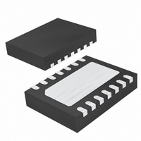
LTC4263IDE-1#TRPBF Linear Technology, LTC4263IDE-1#TRPBF Datasheet - Page 11

LTC4263IDE-1#TRPBF
Manufacturer Part Number
LTC4263IDE-1#TRPBF
Description
IC IEEE 803.2AF CNTRLR 14-DFN
Manufacturer
Linear Technology
Type
Power Over Ethernet (PoE)r
Datasheet
1.LTC4263CDE-1PBF.pdf
(20 pages)
Specifications of LTC4263IDE-1#TRPBF
Applications
Power Interface Switch for Power Over Ethernet (PoE) Devices
Voltage - Supply
48V
Operating Temperature
-40°C ~ 85°C
Mounting Type
Surface Mount
Package / Case
14-DFN
Current - Supply
1mA
Interface
IEEE 802.3af
Controller Type
Power Sourcing Equipment Controller (PSE)
Lead Free Status / RoHS Status
Lead free / RoHS Compliant
Available stocks
Company
Part Number
Manufacturer
Quantity
Price
APPLICATIONS INFORMATION
accidentally powered. Disconnect with either AC or DC
methods using the LTC4263-1 is fully compliant and
insures safe power removal after PD disconnect. Com-
mand and control for the LTC4263-1 is handled internally
without the need of a microcontroller, thereby simplifying
system design.
LTC4263-1 OPERATION
Signature Detection
The IEEE 802.3af specifi cation defi nes a specifi c pair-to-
pair signature resistance used to identify a device that
can accept power via its Ethernet connection. When the
port voltage is below 10V, an IEEE 802.3af compliant
PD will have an input resistance of approximately 25kΩ.
Figure 2 illustrates the relationship between the PD sig-
nature resistance and the required resistance ranges the
PSE must accept and reject. According to the IEEE 802.3af
specifi cation, the PSE must accept PDs with signatures
between 19kΩ and 26.5kΩ and may or may not accept
resistances in the two ranges of 15kΩ to 19kΩ and 26.5kΩ
to 33kΩ. The black box in Figure 2 represents the typical
150Ω pair-to-pair termination used in Ethernet devices
like a computer’s network interface card (NIC) that cannot
accept power.
The LTC4263-1 checks for the signature resistance by
forcing two test currents on the port in sequence and
measuring the resulting voltages. It then subtracts the two
V-I points to determine the resistive slope while remov-
ing voltage offset caused by any series diodes or current
offset caused by leakage at the port (see Figure 3). The
LTC4263-1 will typically accept any PD resistance between
17kΩ and 29.7kΩ as a valid PD. Values outside this range
(excluding open and short-circuits) are reported to the
user by a code fl ashed via the LED pin.
RESISTANCE
Figure 2. IEEE 802.3af Signature Resistance Ranges
PSE
PD
0Ω
150Ω (NIC)
REJECT
10k
15k
19k
20k
23.75k
ACCEPT
26.5k
26.25k
30k
33k
REJECT
42631 F02
The LTC4263-1 uses a force-current detection method in
order to reduce noise sensitivity and provide a more robust
detection algorithm. The fi rst test point is taken by forcing
a test current into the port, waiting a short time to allow
the line to settle and measuring the resulting voltage. This
result is stored and the second current is applied to the
port, allowed to settle and the voltage measured.
The LTC4263-1 will not power the port if the PD has more
than 5μF in parallel with its signature resistor unless legacy
mode is enabled.
The LTC4263-1 autonomously tests for a valid PD con-
nected to the port. It repeatedly queries the port every
580ms, or every 3.2s if midspan backoff mode is active
(see below). If detection is successful, it then powers up
the port.
Midspan Backoff
IEEE 802.3af requires the midspan PSE to wait two seconds
after a failed detection before attempting to detect again
unless the port resistance is greater than 500kΩ. This
requirement is to prevent the condition of an endpoint PSE
and a midspan PSE, connected to the same PD at the same
time, from each corrupting the PD signature and prevent-
ing power-on. After the fi rst corrupted detection cycle, the
midspan PSE waits while the endpoint PSE completes
detection and turns the port on. If the midspan mode of
the LTC4263-1 is enabled by connecting the MIDSPAN
pin to V
detect cycle unless the result is an open circuit.
DD5
255
180
, a 3.2 second delay occurs after every failed
OFFSET
0V-2V
Figure 3. PD 2-Point Detection
VALID PD
25k | SLOPE
VOLTAGE
DETECTION
SECOND
POINT
DETECTION
POINT
FIRST
LTC4263-1
42631 F03
11
42631fa


