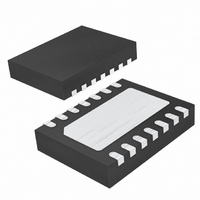
LTC4263IDE-1#TRPBF Linear Technology, LTC4263IDE-1#TRPBF Datasheet - Page 13

LTC4263IDE-1#TRPBF
Manufacturer Part Number
LTC4263IDE-1#TRPBF
Description
IC IEEE 803.2AF CNTRLR 14-DFN
Manufacturer
Linear Technology
Type
Power Over Ethernet (PoE)r
Datasheet
1.LTC4263CDE-1PBF.pdf
(20 pages)
Specifications of LTC4263IDE-1#TRPBF
Applications
Power Interface Switch for Power Over Ethernet (PoE) Devices
Voltage - Supply
48V
Operating Temperature
-40°C ~ 85°C
Mounting Type
Surface Mount
Package / Case
14-DFN
Current - Supply
1mA
Interface
IEEE 802.3af
Controller Type
Power Sourcing Equipment Controller (PSE)
Lead Free Status / RoHS Status
Lead free / RoHS Compliant
Available stocks
Company
Part Number
Manufacturer
Quantity
Price
APPLICATIONS INFORMATION
Thermal Protection
The LTC4263-1 includes thermal overload protection in
order to provide full device functionality in a miniature
package while maintaining safe operating temperatures.
Several factors create the possibility for very large power
dissipation within the LTC4263-1. At port turn-on, while
I
LTC4263-1 can be as high as 18W. This can cause 40ºC or
more of die heating in a single turn-on sequence. Similarly,
excessive heating can occur if an attached PD repeatedly
pushes the LTC4263-1 into I
current. Excessive heating can also occur if the V
is shorted or overloaded.
The LTC4263-1 protects itself from thermal damage by
monitoring die temperature. If the die temperature exceeds
the overtemperature trip point, the LTC4263-1 removes
port power and shuts down all functions including the
internal 5V regulator. Once the die cools, the LTC4263-1
waits four seconds, then restarts detection.
DC Disconnect
The DC disconnect circuit monitors port current whenever
power is on to detect continued presence of the PD. IEEE
802.3af mandates a minimum current of 10mA that the
PD must draw for periods of at least 75ms with optional
dropouts of no more than 250ms. The t
timer increments whenever port current is below 7.5mA
(typ). If the timer expires, the port is turned off and the
LTC4263-1 waits 1.5 seconds before restarting detection.
LIM
is active, the instantaneous power dissipated by the
150
750
600
450
300
0
0
Figure 5. Current Limit Foldback
5
10 15 20 25 30 35
V
DD48
– V
OUT
LIM
(V)
by drawing too much
40
45 50
MPDO
42631 F07
disconnect
DD5
pin
If the undercurrent condition goes away before t
(
nect circuit includes a glitch fi lter to prevent noise from
falsely resetting the timer. The current must be present for
a period of at least 20ms to guarantee reset of the timer.
To enable DC disconnect, tie the OSC pin to V
AC Disconnect
AC disconnect is an alternate method of sensing the pres-
ence or absence of a PD by monitoring the port impedance.
The LTC4263-1 forces an AC signal from an internal sine
wave generator on to the port. The ACOUT pin current is
then sampled once per cycle and compared to I
Like DC disconnect, the AC disconnect sensing circuitry
controls the t
impedance rises due to the removal of the PD, AC peak
current falls below I
ments. If the impedance remains high (AC peak current
remains below I
t
causing AC peak current to rise above I
consecutive samples before the maximum count of the
disconnect timer, the timer resets and the port remains
powered.
The AC disconnect circuitry senses the port via the ACOUT
pin. Connect a 0.47μF 100V X7R capacitor (C
resistor (R
shown in Figure 6. This provides an AC path for sensing
the port impedance. The 1k resistor, R
fl owing through this path during port power-on and power-
off. An AC blocking diode (D
OUT pin and the port to prevent the AC signal from being
shorted by the LTC4263-1’s power control MOSFET. The
500k resistor across D
after disconnect occurs.
Sizing of capacitors is critical to ensure proper function
of AC disconnect. C
impedance on the PSE side. Its capacitance must be kept
low enough for AC disconnect to be able to sense the PD.
On the other hand, C
the signal at 110Hz. The recommended values are 0.1μF
for C
and R
MPDO
350ms (typ)
PSE
DET
and the port is turned off. If the impedance falls,
and 0.47μF for C
are chosen to create an economical, physically
DET
MPDO
)
) from the DETECT pin to the port output as
, the timer is reset to zero. The DC discon-
ACDMIN
disconnect timer. When the connection
ACDMIN
PSE
DET
AC
(Figure 6) controls the connection
), the disconnect timer counts to
has to be large enough to pass
allows the port voltage to decay
and the disconnect timer incre-
DET
AC
. The sizes of C
) is inserted between the
LTC4263-1
DET
ACDMIN
, limits current
DET
SS
PSE
) and a 1k
.
ACDMIN
13
for two
, C
MPDO
42631fa
DET
.
,


