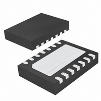
LTC4263IDE-1#TRPBF Linear Technology, LTC4263IDE-1#TRPBF Datasheet - Page 16

LTC4263IDE-1#TRPBF
Manufacturer Part Number
LTC4263IDE-1#TRPBF
Description
IC IEEE 803.2AF CNTRLR 14-DFN
Manufacturer
Linear Technology
Type
Power Over Ethernet (PoE)r
Datasheet
1.LTC4263CDE-1PBF.pdf
(20 pages)
Specifications of LTC4263IDE-1#TRPBF
Applications
Power Interface Switch for Power Over Ethernet (PoE) Devices
Voltage - Supply
48V
Operating Temperature
-40°C ~ 85°C
Mounting Type
Surface Mount
Package / Case
14-DFN
Current - Supply
1mA
Interface
IEEE 802.3af
Controller Type
Power Sourcing Equipment Controller (PSE)
Lead Free Status / RoHS Status
Lead free / RoHS Compliant
Available stocks
Company
Part Number
Manufacturer
Quantity
Price
APPLICATIONS INFORMATION
LTC4263-1
power if the port exceeds 540mA(min). This sets the
maximum system operating current and along with the
working voltage, limits the power available to the PD. The
power at the PSE output is reduced by the resistance of
the LTC4263-1 internal power MOSFET and the voltage
drop of the AC blocking diode if used for AC disconnect
as shown in Figure 8. The cabling can be responsible for
the largest loss. In our example based on a worst-case
100 meter CAT5 cable and connectors, the power loss can
be as much as 3.6W. Obviously for shorter cable runs the
loss is less and lower resistance cables such as CAT6 will
have correspondingly lower losses.
The total power available at the PD can be calculated taking
in to account these losses using the formula:
For many PoE systems, the only parameter affecting power
delivery that is under the control of the PSE designer is the
power supply. Optimum power delivery can be obtained
by maximizing this power supply voltage. 4-pair systems
can be treated as two independent 2-pair systems and
therefore the power will be twice that of the 2-pair.
2-Pair vs 4-Pair
One of the basic architectural decisions associated with
a high power PoE system is whether to deliver power
using four conductors (2-pair) or all eight conductors
16
P
PD
=
(
–
V
(
SUPPLY
V
DAC
•
I
CUT
•
I
55V TO 57V
CUT
V
POWER
SUPPLY
SUPPLY
)
–
)
P
(
–
LOSS_4263-1(MAX)
I I
POWER (MIN)
= 55V (MIN) • 540mA (MIN)
= 29.7W (MIN)
= (540mA)
CUT
(
= 0.9W (MAX)
Figure 8. Example of Power Delivery Calculation Using the LTC4263-1
I
CUT
2
•
2
2
I
R
CUT(MIN)
• 3Ω
•
R
CABLE
ON(MAX)
R
LTC4263-1
ON
= 540mA
)
= 3Ω
)
DISCONNECT
(OPTIONAL)
DIODE
AC
P
= 0.5V • 540mA
= 0.3W (MAX)
LOSS_AC DIODE(MAX)
P
= 28.8W (MIN, DC DISCONNECT)
= 28.5W (MIN, AC DISCONNECT)
100M CAT5 CABLE
OUT(MIN)
(4-pair). Each method provides advantages and the
system vendor needs to decide which method best suits
their application.
2-pair power is used today in IEEE 802.3af systems (see
Figure 1). One pair of conductors is used to deliver the
current and a second pair is used for the return while two
conductor pairs are not powered. This architecture offers
the simplest implementation method but suffers from
higher cable loss than an equivalent 4-pair system.
4-pair power delivers current to the PD via two conductor
pairs in parallel (Figure 9). This lowers the cable resis-
tance but raises the issue of current balance between
each conductor pair. Differences in resistance of the
transformer, cable and connectors along with differences
in diode bridge forward voltage in the PD can cause an
imbalance in the currents fl owing through each pair. The
4-pair system in Figure 9 solves this problem by using
two independent DC/DC converters in the PD. Using a
2-pair architecture with the LTC4263-1 allows delivery of
25W to the PD while using a 4-pair architecture allows
delivery of 50W. Contact Linear Technology applications
support for detailed information on implementing 2-pair
and 4-pair PoE systems.
Common Mode Chokes
Both non-powered and powered Ethernet connections
achieve best performance for data transfer and EMI when a
common mode choke is used on each port. For cost reduc-
tion reasons, some designs share a common mode choke
between two adjacent ports. This is not recommended.
12.5Ω (MAX)
CABLE LOSS (MAX)
= (540mA)
= 3.6W
2
• 12.5Ω
P
= 25.2W (MIN, DC DISCONNECT)
= 24.9W (MIN, AC DISCONNECT)
OUT(MIN)
PD
42631 F08
42631fa


