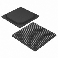
DS33R41+ Maxim Integrated Products, DS33R41+ Datasheet - Page 45

DS33R41+
Manufacturer Part Number
DS33R41+
Description
IC TXRX ETHERNET MAP 400-BGA
Manufacturer
Maxim Integrated Products
Type
Transceiverr
Datasheet
1.DS33R41.pdf
(335 pages)
Specifications of DS33R41+
Number Of Drivers/receivers
4/4
Protocol
T1/E1/J1
Voltage - Supply
3.14 V ~ 3.47 V
Mounting Type
Surface Mount
Package / Case
400-BGA
Lead Free Status / RoHS Status
Lead free / RoHS Compliant
- Current page: 45 of 335
- Download datasheet (2Mb)
9.8.1
Link aggregation requires an external host microprocessor to issue instructions and to monitor the IMUX function of
the device. The host microprocessor is responsible for the following tasks to open a transmit channel:
The host microprocessor is also responsible for the following tasks to open a receive channel:
When in the data phase, if any of the links are detected to be out of frame (OOF), data will be corrupted. The link
initialization procedure must be initiated again. Note that the serial HDLC or X.86 encoded data is sent on 4 T1/E1
links, each link will not have separate HDLC/X.86 encoded data. The HDLC/X.86 encoding and decoding is data is
only available when the device has performed IMUX function. Hence on the line the FCS for a given HDLC packet
could transport on a separate link than the HDLC data.
•
•
•
•
•
•
•
•
Microprocessor Requirements
Configuring
Issuing a link start command through GL.IMXC.
Monitoring the ITSYNC1-4 status from
Monitoring GL.IMXDFDELS.IDDELS0 to ensure that differential delay is not larger than 7.75ms.
Setting GL.IMXCN.SENDE to begin transmitting data after all links are synchronized.
Resetting the queue pointers in GL.C1QPR.
Monitoring the TOOFLS1-4 status from
Monitoring the status of IRSYNC1-4 and setting GL.IMXCN.RXE to receive data.
GL.IMXCN
to control the links participating in the aggregation.
GL.IMXSS
GL.IMXOOFLS
45 of 335
or GL.IMXSLS.
to restart handshaking procedure if needed.
Related parts for DS33R41+
Image
Part Number
Description
Manufacturer
Datasheet
Request
R

Part Number:
Description:
MAX7528KCWPMaxim Integrated Products [CMOS Dual 8-Bit Buffered Multiplying DACs]
Manufacturer:
Maxim Integrated Products
Datasheet:

Part Number:
Description:
Single +5V, fully integrated, 1.25Gbps laser diode driver.
Manufacturer:
Maxim Integrated Products
Datasheet:

Part Number:
Description:
Single +5V, fully integrated, 155Mbps laser diode driver.
Manufacturer:
Maxim Integrated Products
Datasheet:

Part Number:
Description:
VRD11/VRD10, K8 Rev F 2/3/4-Phase PWM Controllers with Integrated Dual MOSFET Drivers
Manufacturer:
Maxim Integrated Products
Datasheet:

Part Number:
Description:
Highly Integrated Level 2 SMBus Battery Chargers
Manufacturer:
Maxim Integrated Products
Datasheet:

Part Number:
Description:
Current Monitor and Accumulator with Integrated Sense Resistor; ; Temperature Range: -40°C to +85°C
Manufacturer:
Maxim Integrated Products

Part Number:
Description:
TSSOP 14/A°/RS-485 Transceivers with Integrated 100O/120O Termination Resis
Manufacturer:
Maxim Integrated Products

Part Number:
Description:
TSSOP 14/A°/RS-485 Transceivers with Integrated 100O/120O Termination Resis
Manufacturer:
Maxim Integrated Products

Part Number:
Description:
QFN 16/A°/AC-DC and DC-DC Peak-Current-Mode Converters with Integrated Step
Manufacturer:
Maxim Integrated Products

Part Number:
Description:
TDFN/A/65V, 1A, 600KHZ, SYNCHRONOUS STEP-DOWN REGULATOR WITH INTEGRATED SWI
Manufacturer:
Maxim Integrated Products

Part Number:
Description:
Integrated Temperature Controller f
Manufacturer:
Maxim Integrated Products

Part Number:
Description:
SOT23-6/I°/45MHz to 650MHz, Integrated IF VCOs with Differential Output
Manufacturer:
Maxim Integrated Products

Part Number:
Description:
SOT23-6/I°/45MHz to 650MHz, Integrated IF VCOs with Differential Output
Manufacturer:
Maxim Integrated Products

Part Number:
Description:
EVALUATION KIT/2.4GHZ TO 2.5GHZ 802.11G/B RF TRANSCEIVER WITH INTEGRATED PA
Manufacturer:
Maxim Integrated Products

Part Number:
Description:
QFN/E/DUAL PCIE/SATA HIGH SPEED SWITCH WITH INTEGRATED BIAS RESISTOR
Manufacturer:
Maxim Integrated Products
Datasheet:


