HS7A-DMC7902 IDEC, HS7A-DMC7902 Datasheet - Page 6
HS7A-DMC7902
Manufacturer Part Number
HS7A-DMC7902
Description
NON-CONTACT SAFETY INTERLOCK SWITCH, DPST-NC, 24VDC
Manufacturer
IDEC
Datasheet
1.HS7A-DMC5902.pdf
(7 pages)
Specifications of HS7A-DMC7902
Contact Configuration
DPST-NC
Contact Voltage Dc Max
24V
Contact Current Dc Max
100mA


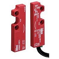
HS7A-DMP Non-contact Interlock Switches
Wiring Diagram
690
Safety Category 4 (EN 954-1) Circuit
HR1S-DMB + HS7A-DMP50 (1NO+2NC) + HS9Z-ZP1
Safety Category 4 (EN 954-1) Circuit
HR1S-DME + HS7A-DMP50 (1NO+2NC) + HS9Z-ZP1
Safety Category 4 (EN 954-1) Circuit
HR1S-AF + HS7A-DMP70 (2NO+1NC) + HS9Z-ZP1
L (+)
24V
ESC: External Start Condition
+24V
0V
ESC: External Start Condition
0V
+24V
ESC: External Start Condition
A1
A2
N (–)
The following diagrams show the contact statuses when the non-contact interlock switches are activated by the actuators .
F1
HR1S-DME
A1
A2
DC
HR1S-DMB
F1
F1
DC
DC
HR1S-AF
A2
DC
F
+24V
F
+24V
S11
S21
Guard 2: Closed
Guard 1: Closed
HS7A-DMP
HS7A-DMP
+24V
+24V
S1
S2
S11
Guard: Closed
F
F
Monitor Signal (to PLC)
Monitor Signal (to PLC)
HS7A-DMP
K3
K4
Power A1/A2
Fault
K1/K2
S33
Guard 1: Closed
Guard 2: Closed
S11
S21
ESC
S22 S23
S12 S13
Power A1/A2
Fault
K1/K2
Power A1/A2
Fault
K1/K2
HS7A-DMP
HS7A-DMP
S2
Start Switch
S21
S1
S34: Start switch welding is detected
S39: Start switch welding is not detected
S34
F
+24V
F
+24 V
S22
S2
LOGIC
S31
S41
S12
S22 S23
LOGIC
LOGIC
Guard 4: Closed
Guard 3: Closed
HS7A-DMP
S3
HS7A-DMP
S4
S13
S12
Monitor Signal (to PLC)
Monitor Signal (to PLC)
Monitor Signal (to PLC)
S39
+24V
Monitor Signal (to PLC)
F
Monitor Signal
(to PLC)
K1
K2
Start Switch
S32 S33
S42 S43
Failure
K3
S3
S13
S12
S23
S22
13
14
F
+24V
F
Y34
+24 V
Y1
S51
S61
ESC
Safety
Output
Guard 5: Closed
HS7A-DMP
HS7A-DMP
Guard 6: Closed
K4
S5
S6
S33
S32
S43
S42
K1/K2
Monitor Signal (to PLC)
Monitor Signal (to PLC)
23
24
K3
K4
S52 S53
S62
S53
S52
S63
S62
Y44
To PLC
Y2
Failure
34
33
K2
Y34
K1
Y1
ESC
Channel 1
Start Switch
F1: Protection fuse for the power of safety relay module
F: Protection fuse for monitor signal contacts (max . 500mA gG (gL))
K1/K2
S7
K3
Safety Output
K3
K4
13
Y44
14
Y2
Channel 1 Channel 2
To PLC
Safety Output
K1
K2
Note: The circuit example shown on the left (HR1S-AF and
K4
Channel 2
23
24
K3
13
14
K4
HS7A-DMP70) may not conform to safety cate-
gory 4 depending on the operating conditions, such
as the frequency of safety function check . Perform
risk assessment of your system before operation .
23
24
Safety Category 3 (EN 954-1) Circuit
HR1S-DMB
Safety Category 3 (EN 954-1) Circuit
HR1S-DME
F
F
S11
S11
HS7A-DMP
HS7A-DMP
HS7A-DMP
HS7A-DMP
HS7A-DMP
HS7A-DMP
S1 .1
S1 .2
S1 .3
S1 .1
S1 .2
S1 .3
S12 S13
S12 S13
Short-circuit unused input terminals .
Short-circuit unused input terminals .
Or:
+24V
+24V
S21
S21
S61
F
F
S21
S21
HS7A-DMP
S2 .2
HS7A-DMP
S2 .3
HS7A-DMP
HS7A-DMP
S2 .2
HS7A-DMP
HS7A-DMP
S2 .1
S2 .1
S2 .3
S22
S22
S62
S22
S22
S23
S23
S63
S23
S23
Related parts for HS7A-DMC7902
Image
Part Number
Description
Manufacturer
Datasheet
Request
R

Part Number:
Description:
NON-CONTACT SAFETY INTERLOCK SWITCH, SPST-NO/SPST-NC, 24VDC
Manufacturer:
IDEC
Datasheet:
Part Number:
Description:
NON-CONTACT SAFETY INTERLOCK SWITCH, SPST-NO/SPST-NC, 24VDC
Manufacturer:
IDEC
Datasheet:
Part Number:
Description:
NON-CONTACT SAFETY INTERLOCK SWITCH, DPST-NC, 24VDC
Manufacturer:
IDEC
Datasheet:

Part Number:
Description:
NON-CONTACT SAFETY INTERLOCK SWITCH, SPST-NO/DPST-NC, 24VDC
Manufacturer:
IDEC
Datasheet:
Part Number:
Description:
NON-CONTACT SAFETY INTERLOCK SWITCH, SPST-NO/DPST-NC, 24VDC
Manufacturer:
IDEC
Datasheet:
Part Number:
Description:
NON-CONTACT SAFETY INTERLOCK SWITCH, DPST-NO/SPST-NC, 24VDC
Manufacturer:
IDEC
Datasheet:
Part Number:
Description:
NON-CONTACT SAFETY INTERLOCK SWITCH, DPST-NO/SPST-NC, 24VDC
Manufacturer:
IDEC
Datasheet:

Part Number:
Description:
Cable; Between IDEC MicroSmart (port 1 or 2) and HG2F/3F/4F; 5 ft.
Manufacturer:
IDEC Corporation
Datasheet:
Part Number:
Description:
Cable; Between IDEC Micro^3C/ONC/MicroSmart (port 2) PLCs and HG2F/3F/4F; 5 ft.
Manufacturer:
IDEC Corporation
Datasheet:
Part Number:
Description:
INDICATOR INCANDESCENT LAMP, GREEN
Manufacturer:
IDEC
Datasheet:

Part Number:
Description:
LAMP, INDICATOR, INCAND, AMB
Manufacturer:
IDEC
Datasheet:
Part Number:
Description:
LAMP, INDICATOR, INCAND, GRN
Manufacturer:
IDEC
Datasheet:
Part Number:
Description:
LAMP, INDICATOR, INCAND, GRN
Manufacturer:
IDEC
Datasheet:
Part Number:
Description:
LAMP, INDICATOR, INCANDESCENT, RED
Manufacturer:
IDEC
Datasheet: