INT-1532-L-5-L-010 TE Connectivity, INT-1532-L-5-L-010 Datasheet
INT-1532-L-5-L-010
Specifications of INT-1532-L-5-L-010


Related parts for INT-1532-L-5-L-010


INT-1532-L-5-L-010 Summary of contents
Page 1
... Integra Digital Metering System a vital part of your world ENERGY DIVISION ...
Page 2
... Integra Digital Metering Systems The Integra product portfolio offers an extensive range of digital metering systems designed to suit any power monitoring application. These multi-function products replace the need for numerous single function instruments, providing significant cost savings and reduced wiring times for all new or retrofit projects. ...
Page 3
... Integra 1530 Integra 2000 Integra 540 Integra 510 2 DIN Integra Digital Metering Specification Overview 96mm (3.78") x 96mm (3.78") Panel cut-out 92mm x 92mm (3.62" IP54 protection Single-phase system Single-phase 3-wire system 3-phase 3-wire system 3-phase 4-wire system 3-phase 4-wire with neutral CT 3-line 4-digit LCD display ...
Page 4
... If customer requirements extend beyond the original specified capabilities, the functionality of this innovative product is easily enhanced to meet new client expectations. Integra plug- in option modules allow cost effective upgrades with any combination of pulsed and digital communication outputs. The option module is interchangeable without recalibration. ...
Page 5
... SCADA systems using the Modbus RTU protocol or the Johnson Controls Metasys NII protocol. Remote monitoring enables the user to record systems parameters in real time, using high resolution numbers. The Integra establishes the format for the master’s query automatically, and responds with the correct protocol using IEEE floating point values ...
Page 6
... Any significant 4-digit integer value up to 400kV ** < 0 (1A option) Any integer value up to 9999A ** 120% nominal 20 x nominal for 1 second, repeated 5 times at 5 minute intervals < 0 maximum CT and VT ratios are limited so that the combination of primary voltage ...
Page 7
Measuring Ranges Voltage: 80-120% of nominal (functional 5-120%) Current: 5-120% of nominal Frequency: 45-66Hz Power factor: 0.8 capacitive–1–0.8 inductive (functional 4 quadrant, 0-1 lag/lead) THD 31st harmonic 0-40% Measured voltage >5% of range Measured current >5% of ...
Page 8
... L – L) Type Features as Factory Default Specified - 4 Wire Pre-configured Spares/Options The functionality of existing Integra 1630 digital metering system products can be easily upgraded with the use of Crompton preconfigured plug-in cards. Option code Description OPT-1630-M- 010 Modbus communications card with 100-250V auxiliary OPT-1630-M-100 ...
Page 9
... If power flows away from the load in an export power situation, then the power will register as exported energy. Auxiliary Supply The Integra 1630 digital metering system should ideally be powered from a dedicated supply: either 100-250 ac, dc (85–280V ac absolute or 85-315V dc absolute), or 12-48V dc (10.2-60V dc absolute) ...
Page 10
... Functionality is easily enhanced to meet new client expectations. Integra pre-calibrated plug-in option cards allow cost effective upgrades with any combination of pulsed, analogue and digital communication outputs. Cards slot simply into the back of the unit and products do not need to be removed from the installation or recalibrated. ...
Page 11
... Modbus connection COM port via a RS485/RS232 converter. Configuration software allows the user to load and save configurations hard disk and to send and retrieve settings directly from the Integra 1530. Settings can also be copied between individual Integra units. Status information is usually communicated into a building management system, but can also be monitored through the configuration software ...
Page 12
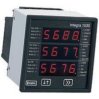
... Programmable Display A two-button interface on the front panel of Integra 1530 units enables the simple programming of VT and CT ratio settings, configuring selected communication options, and adjusting operating parameters. To prevent unauthorised access to configuration settings, all set-up screens offer password protection. Once configured, status information can be viewed by scrolling through 15 screens featuring a high contrast 3-line, 4-digit LED display with separate annunicators for each of the 34 measured parameters ...
Page 13
Accuracy Definition Error change due to variation of an influence quantity in the manner described in section 6 of IEC688:1992 2 * Error allowed for the reference condition applied in the test. Error in measurement when a measured quantity is ...
Page 14
... Pre-calibrated plug-in options Functionality of existing Integra 1530 units can be easily enhanced with Crompton pre-calibrated plug-in cards. OPT-1530-002-1 (0-20mA) OPT-1530-002-3 (-1/0/+1mA) OPT-1530-010 OPT-1530-012-1 (0-20mA) OPT-1530-012-3 (-1/0/+1mA) ...
Page 15
... CT Auxiliary Supply The Integra 1530 should ideally be powered from a dedicated supply, either 100–250V (85–280V ac absolute or 85–312V dc absolute) or 12-48V dc (10.2–60V dc absolute). However the device may be powered from a signal source, provided the source remains within the working range of the chosen auxiliary supply. ...
Page 16
... Operation A five-button menu driven interface on the front panel of Integra 2000 enables the simple programming of VT and CT ratios, configuring selected communication options and adjustment of operating parameters. Integra 2000 provides simple and quick access to the measured electrical data, with active reading screens typically presenting in a 4-line 4-digit format ...
Page 17
... RS485 Johnson Controls, 2 pulse outputs JCA2P2 RS485 Johnson Controls 4/20mA analogue outputs, 2 pulse relays LN0000 Lonworks interface Order Code Example 244-INWW-VRA2-4800P2 - Integra 2000 3-phase 4-wire, input 230V L-N nominal voltage input, 100-250V ac/dc auxiliary, with RS485 Modbus and two pulse relay outputs. ...
Page 18
... System CT primary values: Any value up to 999.9 kA Max continuous input current: 120% nominal Max short duration current input for 1 sec, repeated 5 times at 5 min intervals Nominal input current burden: 0.6VA ** maximum ratios are limited so that the combination of primary voltage and current ...
Page 19
... If current flows away from the load export power situation, then the power factor indication will change to export (EXP). As Integra 2000 serves the full four power factor conditions separate export connections are not required. ...
Page 20
... Model 540 - Three-Phase Maximum Demand Indicator, Ammeter and Voltmeter with Two Maximum Demand Set-Point Relay Outputs Integra 540 offers all the benefits of model 530 plus two programmable set-point trip relay outputs. The incorporation of two output relays allows for early warning alarms, or applications such as selective two-stage load shedding to help prevent higher utility tariffs being imposed ...
Page 21
... Volts L3–L1 20 Programmable Display A two-button interface on the front panel of Integra 500 provides simple programming of device settings and adjustment of operating parameters. Once configured, measurements can be viewed by scrolling through screens featuring a high contrast 3-line, 4-digit LCD display, with annunciators for each screen. Models 530 and 540 offer optional set-point relay outputs, providing maximum demand alarms ...
Page 22
... Max short duration current 20 x for 1 sec., repeated 5 times at 5 min. intervals input for 3 sec., repeated 5 times at 5 min. intervals 5 x for 5 sec., repeated 5 times at 5 min. intervals Nominal input current burden: 0.6 VA approx per phase Relay outputs (530 & 540 only) ...
Page 23
... Connectors offer retained wire protection leaves suitable for one #13 AWG (2.5mm solid or stranded wire. Auxiliary Supply The Integra 500 should ideally be powered from a dedicated supply. However the device may be powered from the signal source, provided this remains within the working range of the chosen auxiliary supply. ...
Page 24
... ANSI Integra Digital Metering ANSI Integra Digital Metering Specification Overview Dimensions 4.31" high x 4.31" wide x 6.7" deep 109.4mm high x 109.4mm wide x 170.2mm deep Configurations 3-phase 3-wire 3-phase 4-wire Measured parameters Voltage line-to-line Voltage line-to-neutral (4-wire only) System voltage Current L1, L2, L3 System current ...
Page 25
... Controls Metasys NII protocol. Remote monitoring enables the user to record the systems parameters in real time, using high resolution numbers. The Modbus protocol establishes the format for the master’s query by placing it into the device address. The slave’s response is also constructed using the Modbus protocol; it contains the fields confirming the action taken, the data to be returned, and an error-checking field ...
Page 26
... RS485 Modbus RTU or Johnson Controls Metasys NII W kWh pulsed output Order Code Example INT-1544-120-5-L-W Integra 1540 3-phase 4-wire, 120V L-L (69.3 L-N) nominal voltage input, 12-48V dc auxiliary supply, with pulsed output option. Measurement, Display and Communication Integra 1540 offers configuration, display and communication electrical and power quality parameters ...
Page 27
... System CT primary values: 9999:5A or 9999:1A max 360MW ** Max continuous input current: 120% nominal Max short duration current input for 1 second, repeated 5 times at 5 second intervals Nominal input current burden: < 0.6VA Outputs RS485 communications: 2-wire half duplex Baud rates: 2400, 4800, 9600, 19200 Pulsed: Clean contact SPNO, 100V dc 0 ...
Page 28
... Controls Metasys NII protocol. Remote monitoring enables the user to record the systems parameters in real time, using high resolution numbers. The Modbus protocol establishes the format for the master’s query by placing it into the device address. The slave’s response is also constructed using the Modbus protocol; it contains the fields confirming the action taken, the data to be returned, and an error-checking field ...
Page 29
... Warm-up time: 1 minute Shock: 30g in 3 planes Vibration: 10-15Hz, 1.5mm peak-to-peak / 15-150Hz @1g Enclosure Integrity (front face only) IP54 Dimensions: 4.31" high x 4.31" wide x 6.7" deep 109.4mm high x 109mm wide x 170.2mm deep Panel cut-out: 4.06" (103mm) diameter, 4 stud positions ...
Page 30
... Integra 1000 3-phase 4-wire, 208V L-L (120V L-N) nominal voltage input, 100-250V ac/dc auxiliary supply, with kWh pulsed output and RS485 Modbus RTU communications option. 077-IJMU-QRA5-P1 Integra 1000 3-phase 3-wire, 208V L-L nominal voltage input, 12-48V dc auxiliary supply, with kWh pulsed output. 29 ...
Page 31
... L-L (57.7-69.3V L-N) LOV 121-240V L-L (70.1-139V L-N) MIV 241-480V L-L (140-277V L-N) HIV 481-600V L-L (278-346V L-N) Auxiliary voltage suffix* L 12-48V dc M 100-250V ac/dc Order Code Example INT-0643-MIV-5-L Integra 0640 3-phase 3-wire, 241-480 V L-L voltage input, 12-48V dc auxiliary supply. ...
Page 32
... Panel cut-out: 4.06" (103mm) diameter, 4 stud positions Measurement and Display Measurement electrical parameters can be programmed and displayed on the Integra 0640 unit. 1 System volts System current System frequency 2 Volts L1–N (4-wire only) Volts L2– ...
Page 33
... L-L (57.7-69.3V L-N) LOV 121-240V L-L (70.1-139V L-N) MIV 241-480V L-L (140-277V L-N) HIV 481-600V L-L (278-346V L-N) Auxiliary voltage suffix* L 12-48V dc M 100-250V ac/dc Order Code Example INT-0443-MIV-5-L Integra 0440 3-phase 3-wire, 241-480 V L-L voltage input, 12-48V dc auxiliary supply. ...
Page 34
... Panel cut-out: 4.06" (103mm) diameter, 4 stud positions Measurement and Display Measurement electrical parameters can be programmed and displayed on the Integra 0440 unit. 1 System volts System current System frequency 2 Volts L1–N (4-wire only) Volts L2– ...
Page 35
... L-L (57.7-69.3V L-N) LOV 121-240V L-L (70.1-139V L-N) MIV 241-480V L-L (140-277V L-N) HIV 481-600V L-L (278-346V L-N) Auxiliary voltage suffix* L 12-48V dc M 100-250V ac/dc Order Code Example INT-0344-MIV-5-L Integra 0340 3-phase 4-wire, 241–480 V L-L voltage input, 12-48V dc auxiliary supply. ...
Page 36
... Panel cut-out: 4.06" (103mm) diameter, 4 stud positions Measurement and Display Measurement electrical parameters can be programmed and displayed on the Integra 0340 unit. 1 System volts System current 2 Volts L1–N (4-wire only) Volts L2–N (4-wire only) Volts L3– ...
Page 37
... N D Auxiliary Supply The Integra family should ideally be powered from a dedicated supply, either 100-250V (85-280V ac Absolute or 85-312V dc Absolute) or 12-48V dc (10.2- 60V dc abolute). However the device may be powered from the signal source, provided the source remains within the working range of the chosen auxiliary supply. ...
Page 38
... Alternatively, an optional menu driven display unit can be used to configure and monitor measured parameters including three-phase voltage and current, and system watts, VAr, VA, power factor, energy and total harmonic distortion. This Integra Display unit can be permanently panel mounted locally to the transducer, or simply connected at times when configuration, adjustment and/or status information is required ...
Page 39
... PC COM port via a RS485/RS232 converter. Configuration software allows the user to load and save configurations hard disk and to send and retrieve settings directly from the Integra 1530. Settings can also be copied between individual Integra units. Status information is usually communicated into a building management system, but can also be monitored through the configuration software ...
Page 40
... Integra display unit. A simple two-button interface on the front panel of the unit allows display of 32 major electrical and power quality parameters. To prevent unauthorised access to the product settings, all screens can be protected by an optional customer programmable password. ...
Page 41
Accuracy Definition Error change due to variation of an influence quantity as described in section 6 of IEC688:1992. THD accuracy relates to a typical harmonic profile. 40 Specifications Continued Auxilliary Standard nominal supply voltage: 100-250V (85-287V ac ...
Page 42
... INT-1563-*-**-***-option-# Integra 1560 3-phase 3-wire, DIN rail INT-1564-*-**-***-option-# Integra 1560 3-phase 4-wire, DIN rail INT-1565-*-**-***-option-# Integra 1560 3-phase 4-wire with neutral CT, DIN rail INT-1581-*-**-***-option-# Integra 1580 single-phase, base mount INT-1582-*-**-***-option-# Integra 1580 single-phase 3-wire, base mount ...
Page 43
... Integra 1560 Integra 1580 Optional Remote Display 42 Dimensions Integra 1560 DIN Rail Mounted Transducer Integra 1580 Base Mounted Transducer Optional Remote Display (for use with Integra 1560 or 1580 Transducer) Optional Remote Display Panel cut-out ...
Page 44
... P1 DIS-1540 Remote Display Auxiliary Supply The Integra family should ideally be powered from a dedicated supply, either 100-250V (85-280V ac absolute or 85-312V dc absolute) or 12-48V dc (10.2-60V dc absolute). However the device may be powered from the signal source, provided the source remains within the working range of the chosen auxiliary supply. ...
Page 45
PE 201 PE 301 PE 401 44 Accessories CT Accessories The Crompton Instruments, business unit of Tyco Electronics also offers a complete range of high quality current transformers offering comprehensive measuring and protection class accuracies. The range offers a wide ...
Page 46
Product code Ratio range PE601 400/5 PE601 500/5 PE601 600/5 PE601 800/5 PE601 1000/5 PE601 1200/5 PE601 1500/5 PE601 1600/5 PE801 400/5 PE801 500/5 PE801 600/5 PE801 800/5 PE801 1000/5 PE801 1200/5 PE801 1500/5 PE801 1600/5 ...
Page 47
... Access to Integra programmable parameters is password protected, however, settings and the electrical measurements can be viewed without entering the password. The access passwords entered on the PC must be identical to those stored inside the Integra. Operation INT-SOFT is designed to provide two basic functions: to display and configure the parameters of an Integra unit, and to monitor the measured values of the selected Integra ...
Page 48
... RS485 converter which fits into any PC based system. This port powered two-channel module converts the TD and RD RS232 lines into balanced half-duplex RS485 signals via a 9 way female D type connector on the RS232 side, and a screw-clamp terminal block connector on the RS-485 side. The module has an internal connection to prevent data transmitted from the RS232 port being echoed back ...
Page 49
... Abbreviation for Amps Demand. Demand is the rate at which energy is used, and the measurement is averaged over an adjustable demand interval. This ensures short periods of intense use, such as motor start-up, have minimal impact on readings. Instantaneous load currents can be difficult to read when fluctuating averaged demand figure is useful for checking that operations are within the capability of the switchgear and cables ...
Page 50
... This measurement is useful to check reactive losses in a system. kWD Abbreviation for Kilowatt Demand, a measurement that shows the average real power requirement of the kilowatt load over a defined time interval, Max kWD Abbreviation for Maximum Kilowatt Demand, a measurement that shows the highest real power requirement of the maximum recorded average kilowatt load ...
Page 51
... Traditional 3- phase system meters are only able to calculate the vector of line-to-neutral current measurements, which may not register the true reading. Integra 1530, 1560 and 1580 offer a 3-phase 4-wire version with a neutral 4th CT allowing true neutral current measurement and protection in high harmonic environments ...
Page 52
Notes 51 ...
Page 53
Notes 52 ...
Page 54
... Tyco Electronics CI-EPP-IntegraS-06/06 All of the above information, including drawings, illustrations and graphic design, reflects our present understanding and is to the best of our knowledge and belief correct and reliable. Users, however, should independently evaluate the suitability of each product for the desired application ...