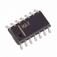
MAX13184EESD+ Maxim Integrated Products, MAX13184EESD+ Datasheet - Page 12

MAX13184EESD+
Manufacturer Part Number
MAX13184EESD+
Description
IC TXRX RS-485 +5.0V ESD 14SOIC
Manufacturer
Maxim Integrated Products
Type
Transceiverr
Datasheet
1.MAX13182EELBT.pdf
(18 pages)
Specifications of MAX13184EESD+
Number Of Drivers/receivers
1/1
Protocol
RS485
Voltage - Supply
4.5 V ~ 5.5 V
Mounting Type
Surface Mount
Package / Case
14-SOIC (3.9mm Width), 14-SOL
Lead Free Status / RoHS Status
Lead free / RoHS Compliant
Figure 7a shows the Human Body Model, and Figure 7b
shows the current waveform it generates when discharged
into a low impedance. This model consists of a 100pF
capacitor charged to the ESD voltage of interest, which is
then discharged into the test device through a 1.5kΩ resistor.
The IEC 61000-4-2 standard covers ESD testing and
performance of finished equipment. However, it does
not specifically refer to integrated circuits. The
MAX13485E/MAX13486E help equipment designs to
meet IEC 61000-4-2, without the need for additional
ESD protection components.
The major difference between tests done using the
Human Body Model and IEC 61000-4-2 is higher peak
current in IEC 61000-4-2 because series resistance is
lower in the IEC 61000-4-2 model. Hence, the ESD with-
stand voltage measured to IEC 61000-4-2 is generally
lower than that measured using the Human Body
Model. Figure 7c shows the IEC 61000-4-2 model, and
Figure 7d shows the current waveform for the IEC
61000-4-2 ESD Contact Discharge test.
+5.0V, ±15kV ESD-Protected, Half-Duplex/
Full-Duplex, RS-485 Transceiver in µDFN
Figure 7a. Human Body ESD Test Model
Figure 7c. IEC 61000-4-2 ESD Test Model
12
VOLTAGE
VOLTAGE
SOURCE
______________________________________________________________________________________
SOURCE
HIGH-
HIGH-
DC
DC
CHARGE-CURRENT-
CHARGE-CURRENT-
LIMIT RESISTOR
LIMIT RESISTOR
50MΩ TO 100MΩ
1MΩ
R
R
C
C
100pF
150pF
C s
C s
RESISTANCE
DISCHARGE
STORAGE
CAPACITOR
RESISTANCE
STORAGE
CAPACITOR
DISCHARGE
1500Ω
330Ω
R
R
D
D
Human Body Model
Machine Model
DEVICE
UNDER
TEST
DEVICE
UNDER
TEST
The standard RS-485 receiver input impedance is 12kΩ
(one-unit load), and the standard driver can drive up to 32
unit loads. The MAX13181E–MAX13184E family trans-
ceivers have a 1/8-unit load receiver input impedance
(96kΩ), allowing up to 256 transceivers to be connected
in parallel on one communication line. Any combination of
these devices and/or other RS-485 transceivers with a
total of 32 unit loads or less can be connected to the line.
The MAX13181E/MAX13182E are slew-rate limited, min-
imizing EMI and reducing reflections caused by improp-
erly terminated cables. This slew-rate limited feature
allows error-free data transmission up to 250kbps.
The MAX13181E/MAX13183E feature low power shut-
down mode. Low-power shutdown mode is initiated by
bringing RE high and DE low. In shutdown, the devices
typically draw only 2.5µA (typ) of supply current. RE
and DE can be driven simultaneously. If RE is high and
Figure 7b. Human Body Current Waveform
Figure 7d. IEC 61000-4-2 ESD Generator Current Waveform
AMPS
t
r
= 0.7ns TO 1ns
I
P
36.8%
100%
90%
10%
MAX13181E/MAX13183E Low-Power
0
100%
0
90%
10%
I
t
RL
Applications Information
Reduced EMI and Reflections
256 Transceiver on the Bus
30ns
CURRENT WAVEFORM
TIME
t
DL
60ns
I r
Shutdown Mode
PEAK-TO-PEAK RINGING
(NOT DRAWN TO SCALE)
t


