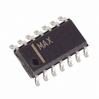
MAX13184EESD+ Maxim Integrated Products, MAX13184EESD+ Datasheet - Page 4

MAX13184EESD+
Manufacturer Part Number
MAX13184EESD+
Description
IC TXRX RS-485 +5.0V ESD 14SOIC
Manufacturer
Maxim Integrated Products
Type
Transceiverr
Datasheet
1.MAX13182EELBT.pdf
(18 pages)
Specifications of MAX13184EESD+
Number Of Drivers/receivers
1/1
Protocol
RS485
Voltage - Supply
4.5 V ~ 5.5 V
Mounting Type
Surface Mount
Package / Case
14-SOIC (3.9mm Width), 14-SOL
Lead Free Status / RoHS Status
Lead free / RoHS Compliant
+5.0V, ±15kV ESD-Protected, Half-Duplex/
Full-Duplex, RS-485 Transceiver in µDFN
DRIVER SWITCHING CHARACTERISTICS—MAX13183E/MAX13184E (MAXIMUM DATA
RATE OF 16Mbps)
(V
RECEIVER SWITCHING CHARACTERISTICS
(V
Note 1: All currents into the device are positive. All currents out of the device are negative. All voltages are referred to device ground,
Note 2: ΔV
Note 3: The short-circuit output current applies to peak current just prior to foldback current limiting. The short-circuit foldback output
4
Driver Propagation Delay
D r i ver D i ffer enti al Outp ut Ri se or Fal l Ti m e
Differential Driver Output Skew
(t
Maximum Data Rate
Driver Enable to Output-High
Driver Enable to Output-Low
Driver Disable Time from Low
Driver Disable Time from High
Driver Enable from Shutdown to Output
High
Driver Enable from Shutdown to Output
Low
Time to Shutdown
Receiver Propagation Delay
Receiver Output Skew (t
Maximum Data Rate
Receiver Enable to Output Low
Receiver Enable to Output High
Receiver Disable Time from Low
Receiver Disable Time from High
Receiver Enable from Shutdown to
Output High
Receiver Enable from Shutdown to
Output Low
CC
DPLH
CC
_______________________________________________________________________________________
= +5V ±10%, T
= +5V ±10%, T
- t
unless otherwise noted. µDFN devices are production tested at +25°C. Overtemperature limits are guaranteed by design.
current applies during current limiting to allow a recovery from bus contention.
DPHL
OD
PARAMETER
)
PARAMETER
and ΔV
A
A
OC
=T
=T
RPLH
MIN
MIN
are the changes in V
to T
to T
- t
RPHL
MAX
MAX
, unless otherwise noted. Typical values are at V
, unless otherwise noted. Typical values are at V
)
t
t
t
t
DZH (SHDN)
DZL (SHDN)
RZH (SHDN)
RZL (SHDN)
SYMBOL
SYMBOL
OD
t
t
t
DR
DSKEW
t
t
t
RSKEW
t
t
t
t
SHDN
DPLH
DPHL
t
t
RPLH
RPHL
t
t
t
t
DZH
DHZ
DZL
DLZ
RZH
RHZ
RZL
RLZ
and V
, t
DF
OC
, respectively, when the DI input changes state.
C
C
C
C
Figures 1 and 4a
Figures 1 and 4b
Figures 1 and 4b
Figures 1 and 4a
Figures 1 and 4a (MAX13184E)
Figures 1 and 4b (MAX13184E)
(MAX13184E)
C
C
(MAX13182E/MAX13184E)
Figures 2 and 6
(MAX13182E/MAX13184E)
Figures 2 and 6
(MAX13182E/MAX13184E)
Figures 2 and 6
(MAX13182E/MAX13184E)
Figures 2 and 6
(MAX13182E/MAX13184E)
Figures 2 and 6
(MAX13182E/MAX13184E)
Figures 2 and 6
L
L
L
L
L
L
= 50pF, R
= 50pF, R
= 50pF, R
= 50pF, R
= 15pF, Figure 5
= 15pF, Figure 5
CONDITIONS
CONDITIONS
L
L
L
L
= 54Ω, Figure 3
= 54Ω, Figure 3
= 54Ω, Figure 3
= 54Ω, Figure 3
CC
CC
= +5V and T
= +5V and T
MIN
MIN
16
50
16
A
A
= +25°C.) (Note 1)
= +25°C.) (Note 1)
TYP
TYP
200
40
40
MAX
2200
2200
MAX
2200
2200
600
25
25
15
50
50
50
50
75
75
50
50
50
50
8
8
UNITS
UNITS
Mbps
Mbps
ns
ns
ns
ns
ns
ns
ns
ns
ns
ns
ns
ns
ns
ns
ns
ns
ns
ns


