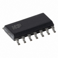
TJA1041AT/N,112 NXP Semiconductors, TJA1041AT/N,112 Datasheet - Page 7

TJA1041AT/N,112
Manufacturer Part Number
TJA1041AT/N,112
Description
IC TXRX CAN 14BIT 27V SOT108-1
Manufacturer
NXP Semiconductors
Type
Transceiverr
Datasheet
1.TJA1041ATVM518.pdf
(25 pages)
Specifications of TJA1041AT/N,112
Number Of Drivers/receivers
1/1
Protocol
CAN
Voltage - Supply
4.75 V ~ 5.25 V
Mounting Type
Surface Mount
Package / Case
14-SOIC (3.9mm Width), 14-SOL
Lead Free Status / RoHS Status
Lead free / RoHS Compliant
Other names
935277288112
TJA1041AT/N
TJA1041AT/N
TJA1041AT/N
TJA1041AT/N
NXP Semiconductors
TJA1041A_4
Product data sheet
7.1.3 Standby mode
7.1.4 Go-to-sleep command mode
7.1.5 Sleep mode
7.2 Internal flags
The Standby mode is the first-level power saving mode of the transceiver, offering reduced
current consumption. In Standby mode the transceiver is not able to transmit or receive
data and the low-power receiver is activated to monitor bus activity. The bus pins are
biased at ground level (via R
by this pin INH will be active too.
Pins RXD and ERR will reflect any wake-up requests (provided that V
present).
The Go-to-sleep command mode is the controlled route for entering Sleep mode. In
Go-to-sleep command mode the transceiver behaves as if in Standby mode, plus a
Go-to-sleep command is issued to the transceiver. After remaining in Go-to-sleep
command mode for the minimum hold time (t
The transceiver will not enter the Sleep mode if the state of pins STB or EN is changed or
the UV
The Sleep mode is the second-level power saving mode of the transceiver. Sleep mode is
entered via the Go-to-sleep command mode, and also when the undervoltage detection
time on either V
the transceiver still behaves as described for Standby mode, but now pin INH is set
floating. Voltage regulators controlled by pin INH will be switched off, and the current into
pin V
wake-up flag and (as long as the UV
The TJA1041A makes use of seven internal flags for its fail-safe fallback mode control and
system diagnosis support.
of the transceiver. Five of the internal flags can be made available to the controller via
pin ERR.
describe the seven internal flags.
Table 5.
Internal
flag
UV
UV
pwon
wake-up
NOM
BAT
BAT
BAT
is reduced to a minimum. Waking up a node from Sleep mode is possible via the
Table 5
, pwon or wake-up flag is set before t
Accessing internal flags via pin ERR
Flag is available on pin ERR
no
no
in Pwon/Listen-only mode (coming from
Standby mode, Go-to-sleep command
mode, or Sleep mode)
in Standby mode, Go-to-sleep command
mode, and Sleep mode (provided that V
and V
CC
shows the details on how to access these flags. The following sections
CC
or V
are present)
I/O
Rev. 04 — 29 July 2008
elapses before that voltage level has recovered. In Sleep mode
Table 4
i(cm)
). Pin INH is still active, so voltage regulators controlled
shows the relation between flags and operating modes
NOM
[1]
flag is not set) via pin STB.
h(min)
h(min)
I/O
), the transceiver will enter Sleep mode.
has expired.
Flag is cleared
by setting the pwon or wake-up flag
when V
on entering Normal mode
on entering Normal mode, or by setting
the pwon or UV
High-speed CAN transceiver
BAT
has recovered
NOM
TJA1041A
I/O
flag
© NXP B.V. 2008. All rights reserved.
and V
CC
are
7 of 25


