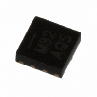
MPR032EPR2 Freescale Semiconductor, MPR032EPR2 Datasheet - Page 6

MPR032EPR2
Manufacturer Part Number
MPR032EPR2
Description
IC CTLR TOUCH SENSOR 8-DFN
Manufacturer
Freescale Semiconductor
Type
Capacitiver
Specifications of MPR032EPR2
Touch Panel Interface
2-Wire
Data Interface
I²C, Serial
Data Rate/sampling Rate (sps, Bps)
400k
Voltage - Supply
1.71 V ~ 2.75 V
Current - Supply
43µA
Operating Temperature
-40°C ~ 85°C
Mounting Type
Surface Mount
Package / Case
8-UDFN
Output Type
Logic
Interface
I²C
Input Type
Logic
Supply Current
8µA
Ic Interface Type
I2C
Supply Voltage Range
1.71V To 2.75V
Sensor Case Style
µDFN
No. Of Pins
8
Operating Temperature Range
-40°C To +85°C
Interface Type
I2C
Rohs Compliant
Yes
Lead Free Status / RoHS Status
Lead free / RoHS Compliant
Other names
MPR032EPR2TR
Available stocks
Company
Part Number
Manufacturer
Quantity
Price
Company:
Part Number:
MPR032EPR2
Manufacturer:
VISHAY
Quantity:
9 073
MPR03X
6
2.3.6
A write to the MPR03X comprises the transmission of the MPR03X’s keyscan slave address with the R/W bit set to 0, followed
by at least one byte of information. The first byte of information is the command byte. The command byte determines which
register of the MPR03X is to be written by the next byte, if received. If a STOP condition is detected after the command byte is
received, the MPR03X takes no further action
command byte are data bytes.
Any bytes received after the command byte are data bytes. The first data byte goes into the internal register of the MPR03X
selected by the command byte
If multiple data bytes are transmitted before a STOP condition is detected, these bytes are generally stored in subsequent
MPR03X internal registers because the command byte address generally auto-increments
2.3.7
MPR03X is read using MPR03X's internally stored register address as address pointer, the same way the stored register address
is used as address pointer for a write. The pointer generally auto-increments after each data byte is read using the same rules
as for a write
followed by a repeated start. The master can now read 'n' consecutive bytes from MPR03X, with first data byte being read from
the register addressed by the initialized register address.
S
S
Message Format for Writing the MPR03X
Message Format for Reading the MPR03X
Command byte is stored on receipt ofSTOP condition
(Table
SLAVE ADDRESS
How command byte and data byte
acknowledge from MPR03X
S
map into MPR03X's registers
5). Thus, a read is initiated by first configuring MPR03X's register address by performing a write
SLAVE ADDRESS
acknowledge from MPR03X
R/W
(Figure
acknowledge from MPR03X
SLAVE ADDRESS
Figure 11. Command and Single Data Byte Received
0
11).
A
Figure 10. Command Byte Received
D15 D14 D13 D12 D11 D10 D9
R/W
(Figure
R/W
Figure 12. Reading MPR03X
0
1
10) beyond storing the command byte. Any bytes received after the
COMMAND BYTE
A
A
D7 D6
D15
acknowledge from
D14
MPR03X
D5 D4
acknowledge from master
DATA BYTE
n bytes
D8
D13
COMMAND BYTE
D3 D2
A
D12
D7
auto-increment memory
acknowledge from MPR3X
D1 D0
D6
D11
word address
(Section
D5
D10
DATA BYTE
A
D4
1 byte
2.4).
Freescale Semiconductor
P
D9
D3
acknowledge from
D2
auto-increment memory
D8
MPR03X
D1
word address
A
D0
(Figure 10)
Sensors
A
P
P


