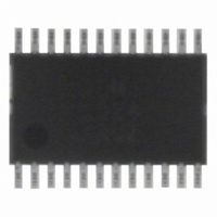
ADM1024ARUZ ON Semiconductor, ADM1024ARUZ Datasheet - Page 17

ADM1024ARUZ
Manufacturer Part Number
ADM1024ARUZ
Description
IC MONITOR SYS TEMP/VOLT 24TSSOP
Manufacturer
ON Semiconductor
Datasheet
1.ADM1024ARUZ.pdf
(29 pages)
Specifications of ADM1024ARUZ
Applications
PC's, PDA's
Interface
Serial
Voltage - Supply
2.8 V ~ 5.5 V
Package / Case
24-TSSOP
Mounting Type
Surface Mount
Temperature Sensor Function
Temp Sensor
Output Type
Digital
Package Type
TSSOP
Operating Temperature (min)
0C
Operating Temperature (max)
100C
Operating Temperature Classification
Commercial
Operating Supply Voltage (typ)
3.3V
Operating Supply Voltage (max)
5.5V
Full Temp Accuracy
+/- 2 C , +/- 3 C
Digital Output - Bus Interface
SMBus
Digital Output - Number Of Bits
10 bit
Supply Voltage (max)
12 V
Supply Voltage (min)
2.5 V
Maximum Operating Temperature
+ 100 C
Minimum Operating Temperature
0 C
Supply Current
1.4 mA
Lead Free Status / RoHS Status
Lead free / RoHS Compliant
Available stocks
Company
Part Number
Manufacturer
Quantity
Price
Part Number:
ADM1024ARUZ
Manufacturer:
ADI/亚德诺
Quantity:
20 000
a totem−pole output, then a series resistor can be added to
limit the Zener current, as shown in Figure 27. Alternatively,
a resistive attenuator may be used, as shown in Figure 28.
2.0 V t V
160 kW to ground, so this should be taken into account when
calculating resistor values.
1 kW, suitable values for R1 and R2 would be 100 kW and
47 kW. This will give a high input voltage of 3.83 V.
Fan Speed Measurement
pulses directly because the fan speed may be less than
1000 rpm and it would take several seconds to accumulate
a reasonably large and accurate count. Instead, the period of
the fan revolution is measured by gating an on−chip
22.5 kHz oscillator into the input of an 8−bit counter for two
periods of the fan tachometer output, as shown in Figure 29;
the accumulated count is actually proportional to the fan
tachometer period and inversely proportional to the fan
speed.
Totem Pole Output, Clamped with Zener and Resistor
If the fan has a strong pullup (less than 1 kW) to 12 V, or
R1 and R2 should be chosen such that:
The fan inputs have an input resistance of nominally
With a pullup voltage of 12 V and pullup resistor less than
The fan counter does not count the fan tachometer output
Figure 28. Fan with Strong Tach Pullup to > V
Figure 27. Fan with Strong Tach Pullup to >V
12V
12V
Totem Pole Output, Attenuated with R1/R2
TYP <1k
PULLUP
TOTEM−POLE
*
<1k W
SEE TEXT.
PULLUP
W
OR
*
CHOOSE ZD1 VOLTAGE APPROXIMATELY 0.8 y V
TACH
OUTPUT
R
R1
PULLUP
*
TACH
OUTPUT
10kW
FAN1 OR
R1
FAN2
R2
R2
) R1 ) R2
*
FAN1 OR
ZD1
ZENER
FAN2
*
160k
V
W
160kW
CC
t 5.0 V
FAN SPEED
COUNTER
V
CC
FAN SPEED
COUNTER
CC
CC
(eq. 7)
http://onsemi.com
or
or
CC
17
Start Bit (Bit 0), and a zero to the INT_Clear Bit (Bit 3) of
the Configuration Register. INT_Enable (Bit 1) should be
set to one to enable the INT output. The measurement begins
on the rising edge of a fan tachometer pulse, and ends on the
next−butone rising edge. The fans are monitored
sequentially, so if only one fan is monitored, the monitoring
time is the time taken after the Start Bit for it to produce two
complete tachometer cycles or for the counter to reach full
scale, whichever occurs sooner. If more than one fan is
monitored, the monitoring time depends on the speed of the
fans and the timing relationship of their tachometer pulses.
This is illustrated in Figure 30. Once the fan speeds have
been measured, they will be stored in the Fan Speed Value
Registers and the most recent value can be read at any time.
The measurements will be updated as long as the monitoring
cycle continues.
numbers of output pulses per revolution, a prescaler
(divisor) of 1, 2, 4, or 8 may be added before the counter. The
default value is 2, which gives a count of 153 for a fan
running at 4400 rpm, producing two output pulses per
revolution.
to have occurred when the speed drops below 70% of
nominal, which would correspond to a count of 219. Full
scale (255) would be reached if the fan speed fell to 60% of
its nominal value. For temperature−controlled variable
speed fans, the situation will be different.
per revolution at 60%, 70%, and 100% of nominal rpm for
fan speeds of 1100, 2200, 4400, and 8800 rpm, and the
divisor that would be used for each of these fans, based on
two tachometer pulses per revolution.
of the VID0–3/Fan Divisor Register.
REG. 1 BIT 0
The monitoring cycle begins when a one is written to the
To accommodate fans of different speed and/or different
The count is calculated by the equation:
For constant speed fans, fan failure is normally considered
Table 5 shows the relationship between fan speed and time
FAN1 and FAN2 Divisors are programmed into Bits 4 to 7
CONFIG.
22.5kHz
CLOCK
INPUT
INPUT
FAN1
FAN2
START OF
MONITORING
CYCLE
Figure 29. Fan Speed Measurement
Count + 22.5
MEASUREMENT
RPM
PERIOD
FAN1
10
Divisor
3
60
MEASUREMENT
PERIOD
FAN2
(eq. 8)


