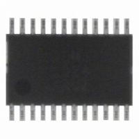
ADM1024ARUZ ON Semiconductor, ADM1024ARUZ Datasheet - Page 23

ADM1024ARUZ
Manufacturer Part Number
ADM1024ARUZ
Description
IC MONITOR SYS TEMP/VOLT 24TSSOP
Manufacturer
ON Semiconductor
Datasheet
1.ADM1024ARUZ.pdf
(29 pages)
Specifications of ADM1024ARUZ
Applications
PC's, PDA's
Interface
Serial
Voltage - Supply
2.8 V ~ 5.5 V
Package / Case
24-TSSOP
Mounting Type
Surface Mount
Temperature Sensor Function
Temp Sensor
Output Type
Digital
Package Type
TSSOP
Operating Temperature (min)
0C
Operating Temperature (max)
100C
Operating Temperature Classification
Commercial
Operating Supply Voltage (typ)
3.3V
Operating Supply Voltage (max)
5.5V
Full Temp Accuracy
+/- 2 C , +/- 3 C
Digital Output - Bus Interface
SMBus
Digital Output - Number Of Bits
10 bit
Supply Voltage (max)
12 V
Supply Voltage (min)
2.5 V
Maximum Operating Temperature
+ 100 C
Minimum Operating Temperature
0 C
Supply Current
1.4 mA
Lead Free Status / RoHS Status
Lead free / RoHS Compliant
Available stocks
Company
Part Number
Manufacturer
Quantity
Price
Part Number:
ADM1024ARUZ
Manufacturer:
ADI/亚德诺
Quantity:
20 000
stored in the Local and Remote Fan Control Registers at
addresses 13h and 14h. The values in these registers cannot
be changed until a power−on reset is performed.
interrupt mode. The default value of 0 selects one−time
mode. Setting this bit to 1 selects ACPI mode.
Starting Conversion
fan speeds) in the ADM1024 is started by writing to
Configuration Register 1 and setting Start (Bit 0) high. The
INT_Enable (Bit 1) should be set to 1, and INT Clear (Bit 3)
set to 0 to enable interrupts. The THERMenable bit (Bit 2)
should be set to 1 and the THERM Clear bit (Bit 6) should
be set to 0 to enable temperature interrupts at the THERM
pin. Apart from initially starting together, the analog
measurements and fan speed measurements proceed
independently, and are not synchronized in any way.
depends on how they are configured, as described
elsewhere. The time taken to complete the fan speed
measurements depends on the fan speed and the number of
tachometer output pulses per revolution.
BATTERY
BACKUP
Bits 1 and 2 of Configuration Register 2 lock the values
Bit 3 of Configuration Register 2 selects the THERM
The monitoring function (analog inputs, temperature, and
The time taken to complete the analog measurements
CMOS
1N914
MRD901
470kW
1
2
3
4
5
6
7
12 V
74HC132
N1
N2
N3
N4
5.0 V
5.0 V
14
13
12
11
10
9
8
100kW
1N914
2N2219A
Figure 37. Application Circuit
10kW
12 V
5.0 V
http://onsemi.com
OP295
5.0 V
39kW
INT TO PROCESSOR
10kW
23
10mF
can be read from the Value Registers at any time.
Reduced Power and Shutdown Mode
setting Bit 0 of the Configuration Register to 0. This disables
the internal ADC. Full shutdown mode may then be
achieved by setting Bit 0 of the Test Register to 1. This turns
off the analog output and stops the monitoring cycle, if
running, but does not affect the condition of any of the
registers. The device will return to its previous state when
this bit is reset to 0.
Application Circuit
ADM1024. The analog monitoring inputs are connected to
the power supplies including two processor core voltage
inputs. The VID inputs are connected to the processor
voltage ID pins. There are two tachometer inputs from fans,
and the analog output is used to control the speed of a third
fan. An opto−sensor for chassis intrusion detection is
connected to the CI input. Of course, in an actual
application, every input and output may not be used, in
which case unused analog and digital inputs should be tied
to analog or digital ground as appropriate.
RESET
THERM I/O TO
OTHER CIRCUITS
SERIAL BUS
Once the measurements have been completed, the results
The ADM1024 can be placed in a low power mode by
Figure 37 shows a generic application circuit using the
NTEST_OUT/ADD
NTEST_IN/AOUT
SDA
SCL
+
0.1mF
10kW
FAN1/AIN1
FAN2/AIN2
THERM
GND D
V
V
INT
CC
CI
CC
10
11
12
1
2
3
4
5
6
7
8
9
ADM1024
24
23
22
21
20
19
18
17
16
15
14
13
D1+
D1–
510kW
510kW
510kW
510kW
510kW
VID0/IRQ0
VID1/IRQ1
VID2/IRQ2
VID3/IRQ3
VID4/IRQ4
+V
+2.5V
+V
+5.0V
+12V
TEMP.
SENSING
TRANSISTOR
CCP1
CCP2
IN
IN
IN
FROM VID
PINS OF
PROCESSOR
/D2+
/D2–


