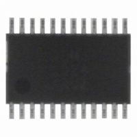
ADM1024ARUZ ON Semiconductor, ADM1024ARUZ Datasheet - Page 25

ADM1024ARUZ
Manufacturer Part Number
ADM1024ARUZ
Description
IC MONITOR SYS TEMP/VOLT 24TSSOP
Manufacturer
ON Semiconductor
Datasheet
1.ADM1024ARUZ.pdf
(29 pages)
Specifications of ADM1024ARUZ
Applications
PC's, PDA's
Interface
Serial
Voltage - Supply
2.8 V ~ 5.5 V
Package / Case
24-TSSOP
Mounting Type
Surface Mount
Temperature Sensor Function
Temp Sensor
Output Type
Digital
Package Type
TSSOP
Operating Temperature (min)
0C
Operating Temperature (max)
100C
Operating Temperature Classification
Commercial
Operating Supply Voltage (typ)
3.3V
Operating Supply Voltage (max)
5.5V
Full Temp Accuracy
+/- 2 C , +/- 3 C
Digital Output - Bus Interface
SMBus
Digital Output - Number Of Bits
10 bit
Supply Voltage (max)
12 V
Supply Voltage (min)
2.5 V
Maximum Operating Temperature
+ 100 C
Minimum Operating Temperature
0 C
Supply Current
1.4 mA
Lead Free Status / RoHS Status
Lead free / RoHS Compliant
Available stocks
Company
Part Number
Manufacturer
Quantity
Price
Part Number:
ADM1024ARUZ
Manufacturer:
ADI/亚德诺
Quantity:
20 000
Table 8. Register 16h, Channel Mode Register (Power−On Default, 00h)
Addr
Hex
3Ah
3Bh
3Ch
3Dh
3Eh
3Fh
4Ah
4Ch
4Dh
35h
36h
37h
38h
39h
40h
41h
42h
43h
44h
46h
47h
49h
Bit
0
1
2
3
4
5
6
7
V
V
Ext. Temp1 High Limit
Ext. Temp1 Low Limit
Internal Temp. High Limit
Internal Temp. Low Limit
A
A
Reserved
Company ID Number
Revision Number
Configuration Register 1
Interrupt INT Status Register 1
Interrupt INT Status Register 2
INT Mask Register 1
INT Mask Register 2
Chassis Intrusion Clear Register
VID0–3/Fan Divisor Register
VID4 Register
Configuration Register 2
Interrupt Status Register Mirror 1
Interrupt Status Register Mirror 2
CCP2
CCP2
IN1
IN2
2.5 V, V
/FAN1 High Limit
/FAN2 High Limit
High Limit
Low Limit
FAN1/A
FAN2/A
IRQ0 EN
IRQ1 EN
IRQ2 EN
VID/IRQ
Int. V
Name
Description
CCP2
CC
IN1
IN2
/D2
R/W
R/W
R/W
R/W
R/W
R/W
R/W
R/W
R/W
Power−On Value
Indeterminate
Indeterminate
Indeterminate
Indeterminate
Indeterminate
Indeterminate
Indeterminate
Indeterminate
Indeterminate
0100 0001
0001 nnnn
0000 1000
0000 0000
0000 0000
0000 0000
0000 0000
0000 0000
0101 (VID3–VID0)
1000 000 (VID4)
0000 0000
0000 0000
0000 0000
(Binary Bit 7−0)
Clearing this bit to 0 configures Pin 5 as FAN1 input. Setting this bit to 1 configures
Pin 5 as AIN1. Power−on default = 0.
Clearing this bit to 0 configures Pin 6 as FAN2 input. Setting this bit to 1 configures
Pin 6 as AIN2. Power−on default = 0.
Clearing this bit to 0 configures Pins 17 and 18 to measure V
this bit to 1 configures Pins 17 and 18 as an input for a second remote
temperature−sensing diode. Power−on default = 0.
Clearing this bit to 0 sets the measurement range for the internal V
to 3.3 V. Setting this bit to 1 sets the internal V
Power−on default = 0.
Setting this bit to 1 enables Pin 24 as an active high interrupt input, provided Pins 20
to 24 have been configured as interrupts by setting Bit 7 of the Channel Mode
Register. Power−on default = 0.
Setting this bit to 1 enables Pin 23 as an active high interrupt input, provided Pins 20
to 24 have been configured as interrupts by setting Bit 7 of the Channel Mode
Register. Power−on default = 0.
Setting this bit to 1 enables Pin 22 as an active high interrupt input, provided Pins 20
to 24 have been configured as interrupts by setting Bit 7 of the Channel Mode
Register. Power−on default = 0.
Clearing this bit to 0 configures Pins 20 to 24 as processor voltage ID inputs. Setting
this bit to 1 configures Pins 20 to 24 as interrupt inputs. Power−on default = 0.
http://onsemi.com
25
Stores high limit for a diode sensor connected to Pins 13 and 14.
Stores low limit for a diode sensor connected to Pins 13 and 14.
Stores the high limit for the internal temperature reading.
Stores the low limit for the internal temperature reading.
Stores high limit for AIN1 or FAN1, depending on the configuration of
Pin 5.
Stores high limit for AIN2 or FAN2, depending on the configuration of
Pin 6.
This location will contain the company identification number (Read
Only).
Last four bits of this location will contain the revision number of the
part (Read Only).
See Table 10
See Table 11
See Table 12
See Table 13
See Table 14
See Table 15
See Table 16
See Table 17
See Table 18
See Table 19
See Table 20
Description
CC
Notes
measurement range to 5.0 V.
CCP2
and 2.5 V. Setting
CC
measurement


