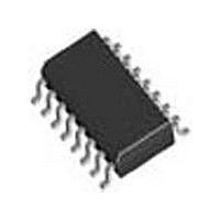
QH25F640S33B8 Micron Technology Inc, QH25F640S33B8 Datasheet - Page 30

QH25F640S33B8
Manufacturer Part Number
QH25F640S33B8
Description
Manufacturer
Micron Technology Inc
Datasheet
1.QH25F640S33B8.pdf
(41 pages)
Specifications of QH25F640S33B8
Cell Type
NOR
Density
64Mb
Interface Type
Serial (SPI)
Boot Type
Bottom
Address Bus
1b
Operating Supply Voltage (typ)
3/3.3V
Operating Temp Range
-40C to 85C
Package Type
SOIC
Sync/async
Synchronous
Operating Temperature Classification
Industrial
Operating Supply Voltage (min)
2.7V
Operating Supply Voltage (max)
3.6V
Word Size
16b
Number Of Words
4M
Supply Current
10mA
Mounting
Surface Mount
Pin Count
16
Lead Free Status / Rohs Status
Compliant
Available stocks
Company
Part Number
Manufacturer
Quantity
Price
Company:
Part Number:
QH25F640S33B8
Manufacturer:
MICRO
Quantity:
3 000
Part Number:
QH25F640S33B8
Manufacturer:
INTEL
Quantity:
20 000
8.2.16
8.3
Datasheet
30
As with any command that writes to the device or changes the memory contents, the
Write Enable command must be executed prior to the Bulk Erase command to set the
WEL bit. The Bulk Erase command will be ignored if the WEL bit is not set.
If the WEL bit is set and there is at least one memory sector that is protected, the erase
operation will not occur. Instead, the E_FAIL flag of the Status Register will set and the
WEL bit will clear.
The Bulk Erase command can be botched (cancelled) by failing to raise the S# edge
after exactly eight clock cycles. If the Bulk Erase command is botched, the WEL bit will
not clear and the E_FAIL flag will not set.
Assuming the WEL bit is set, all memory sectors are unprotected, and the command is
not botched, the rising edge of S# initiates the erase operation. This erase operation
cannot be terminated without powering off the device, and doing so will result in
unexpected data.
Sector Erase Command (D8h)
The Sector Erase command is used to erase a 64-KB memory sector. The command
sequence consists of an 8-bit OP code followed by a 24-bit address. If the address is
within the parameter block address range (A[max:16]=0), all eight parameter blocks
will be erased. (With this characteristic, the device behaves as a symmetrically blocked
device.)
As with any command that writes to the device or changes the memory contents, the
Write Enable command must be executed prior to the Sector Erase command in order
to set the WEL bit. If the WEL bit is not set, the Sector Erase command will be ignored.
If the WEL bit is set and the address is protected, the erase operation will not occur.
Instead, the E_FAIL flag of the Status Register will set and the WEL bit will clear.
The Sector Erase command can be botched (cancelled) by failing to raise the S# edge
after exactly 32 clock cycles. If the Sector Erase command is botched, the WEL bit will
not clear and the E_FAIL flag will not set.
Assuming the WEL bit is set, the address is an unprotected, and the command is not
botched, the rising edge of S# initiates the erase operation. The erase operation cannot
be terminated without powering off the device, and doing so will result in unexpected
data.
Status Register Definition
The Status Register bit definition can be found in
program/erase fail flags, and it contains writeable bits that define the program/erase
protection within the Flash array. All Status Register bits are volatile.
Table
Numonyx™ Serial Flash Memory (S33)
16. The Status Register has
Order Number: 314822-03
December 2007


