PC16552DV/NOPB National Semiconductor, PC16552DV/NOPB Datasheet - Page 11
PC16552DV/NOPB
Manufacturer Part Number
PC16552DV/NOPB
Description
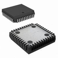
IC UART DUAL WITH FIFO 44-PLCC
Manufacturer
National Semiconductor
Datasheet
1.PC16552DVNOPB.pdf
(22 pages)
Specifications of PC16552DV/NOPB
Features
False-start Bit Detection
Number Of Channels
2, DUART
Fifo's
16 Byte
Voltage - Supply
5V
With False Start Bit Detection
Yes
With Modem Control
Yes
Mounting Type
Surface Mount
Package / Case
44-LCC (J-Lead)
No. Of Channels
2
Data Rate
1.5Mbps
Uart Features
Independently Controlled Transmit, Receive, Line Status, And Data Set Interrupts
Supply Voltage Range
4.5V To 5.5V
Rohs Compliant
Yes
Lead Free Status / RoHS Status
Lead free / RoHS Compliant
Other names
*PC16552DV
*PC16552DV/NOPB
PC16552DV
*PC16552DV/NOPB
PC16552DV
Available stocks
Company
Part Number
Manufacturer
Quantity
Price
Company:

Part Number:
PC16552DV/NOPB
Manufacturer:
TI
Quantity:
7 782
Company:
Part Number:
PC16552DV/NOPB
Manufacturer:
NSC
Quantity:
12 464
Company:
Part Number:
PC16552DV/NOPB
Manufacturer:
Texas Instruments
Quantity:
10 000


6 0 Pin Descriptions
The following describes the function of all DUART pins
Some of these descriptions reference internal circuits
In the following descriptions a low represents a logic 0 (0V
nominal) and a high represents a logic 1 (
Serial channels are designated by a numerical suffix (1 or 2)
after each pin name If a numerical suffix is not associated
with the pin name then the information applies to both
channels
A0 A1 A2 (Register Select) pins 10 14 15 Address sig-
nals connected to these 3 inputs select a DUART register
for the CPU to read from or write to during data transfer
Table I shows the registers and their addresses Note that
the state of the Divisor Latch Access Bit (DLAB) which is
the most significant bit of the Line Control Register affects
the selection of certain DUART registers The DLAB must
be set high by the system software to access the Baud
Generator Divisor Latches and the Alternate Function Reg-
ister
CHSL (Channel Select) pin 16 This directs the address
and data information to the selected serial channel When
CHSL is high channel 1 is selected When CHSL is low
channel 2 is selected
CS (Chip Select) pin 18 When CS is low the chip is select-
ed This enables communication between the DUART and
the CPU Valid chip selects should stabilize according to the
t
CTS1 CTS2 (Clear to Send) pins 40 28 When low this
indicates that the MODEM or data set is ready to exchange
data The CTS signal is a MODEM status input whose con-
dition the CPU can test by reading bit 4 (CTS) of the
MODEM Status Register for the appropriate channel Bit 4
is the complement of the CTS signal Bit 0 (DCTS) of the
MODEM Status Register indicates whether the CTS input
has changed state since the previous reading of the
MODEM Status Register CTS has no effect on the Trans-
mitter
Note Whenever the CTS bit of the MODEM Status Register changes state
D
STATE input output lines The bus provides bidirectional
communications between the UART and the CPU Data
control words and status information are transferred via the
D
DCD1 DCD2 (Data Carrier Detect) pins 42 30 When low
indicates that the data carrier has been detected by the
MODEM or data set The DCD signal is a MODEM status
input whose condition the CPU can test by reading bit 7
(DCD) of the MODEM Status Register for the appropriate
channel Bit 7 is the complement of the DCD signal Bit 3
(DDCD) of the MODEM Status Register indicates whether
the DCD input has changed state since the previous reading
of the MODEM Status Register DCD has no effect on the
receiver
Note Whenever the DCD bit of the MODEM Status Register changes state
DSR1 DSR2 (Data Set Ready) pins 41 29 When low this
indicates that the MODEM or data set is ready to establish
the communications link with the DUART The DSR signal is
a MODEM status input whose condition the CPU can test by
reading bit 5 (DSR) of the MODEM Status Register for the
AW
7
7
–D
–D
parameter
an interrupt is generated if the MODEM Status Interrupt is enabled
an interrupt is generated if the MODEM Status Interrupt is enabled
0
0
(Data Bus) pins 9–2 This bus comprises eight TRI-
Data Bus
a
2 4V nominal)
11
appropriate channel Bit 5 is the complement of the DSR
signal Bit 1 (DDSR) of the MODEM Status Register indi-
cates whether the DSR input has changed state since the
previous reading of the MODEM Status Register
Note Whenever the DSR bit of the MODEM Status Register changes state
DTR1 DTR2 (Data Terminal Ready) pins 37 27 When low
this informs the MODEM or data set that the DUART is
ready to establish a communications link The DTR output
signal can be set to an active low by programming bit 0
(DTR) of the MODEM Control Register to a high level A
Master Reset operation sets this signal to its inactive (high)
state Loop mode operation holds this signal in its inactive
state
INTR1 INTR2 (Interrupt) pins 34 17 This goes high when-
ever any one of the following interrupt types has an active
high condition and is enabled via the IER Receiver Error
Flag Received Data Available timeout (FIFO Mode only)
Transmitter Holding Register Empty and MODEM Status
The INTR signal is reset low upon the appropriate interrupt
service or a Master Reset operation
MF1 MF2 (Multi-Function) pins 35 19 This can be pro-
grammed for any one of three signal functions OUT 2
BAUDOUT or RXRDY Bits 2 and 1 of the Alternate Func-
tion Register select which output signal will be present on
this pin OUT 2 is the default signal and it is selected imme-
diately after master reset or power-up
The OUT 2 signal can be set active low by programming bit
3 (OUT 2) of the associated channel’s MODEM Control
Register to a 1 A Master Reset operation sets this signal to
its inactive (high) state Loop Mode holds this signal in its
inactive state
The BAUDOUT signal is the 16
the transmitter and receiver logic of the associated serial
channel This signal is the result of the XIN clock divided by
the value in the Division Latch Registers The BAUDOUT
signal for each channel is internally connected to provide
the receiver clock (formerly RCLK on the PC16550D)
The RXRDY signal can be used to request a DMA transfer
of data from the RCVR FIFO Details regarding the active
and inactive states of this signal are given in Section 8 5 Bit
3
MR (Master Reset) pin 21 When this input is high it clears
all the registers (except the Receiver Buffer Transmitter
Holding and Divisor Latches) and the control logic of the
DUART The states of various output signals (SOUT INTR
OUT 2 RTS DTR) are affected by an active MR input (Re-
fer to Table III ) This input is buffered with a TTL-compatible
Schmitt Trigger
RD (Read) pin 24 When RD is low while the chip is select-
ed the CPU can read status information or data from the
selected DUART register
RTS1 RTS2 (Request to Send) pins 36 23 When low this
informs the MODEM or data set that the UART is ready to
exchange data The RTS output signal can be set to an
active low by programming bit 1 (RTS) of the MODEM Con-
trol Register A Master Reset operation sets this signal to its
inactive (high) state Loop mode operation holds this signal
in its inactive state
an interrupt is generated if the MODEM Status Interrupt is enabled
c
clock output that drives
Related parts for PC16552DV/NOPB
Image
Part Number
Description
Manufacturer
Datasheet
Request
R

Part Number:
Description:
UART IC
Manufacturer:
National Semiconductor
Datasheet:

Part Number:
Description:
National Semiconductor [8-Bit D/A Converter]
Manufacturer:
National Semiconductor
Datasheet:
Part Number:
Description:
National Semiconductor [Media Coprocessor]
Manufacturer:
National Semiconductor
Datasheet:
Part Number:
Description:
Digitally Controlled Tone and Volume Circuit with Stereo Audio Power Amplifier, Microphone Preamp Stage and National 3D Sound
Manufacturer:
National Semiconductor
Datasheet:
Part Number:
Description:
Digitally Controlled Tone and Volume Circuit with Stereo Audio Power Amplifier, Microphone Preamp Stage and National 3D Sound
Manufacturer:
National Semiconductor
Datasheet:
Part Number:
Description:
AC97 Rev 2 Codec with Sample Rate Conversion and National 3D Sound
Manufacturer:
National Semiconductor
Part Number:
Description:
Manufacturer:
National Semiconductor
Datasheet:
Part Number:
Description:
Manufacturer:
National Semiconductor
Datasheet:
Part Number:
Description:
General Purpose, Low Voltage, Low Power, Rail-to-Rail Output Operational Amplifiers
Manufacturer:
National Semiconductor
Datasheet:
Part Number:
Description:
8-bit 20 MSPS flash A/D converter.
Manufacturer:
National Semiconductor
Datasheet:
Part Number:
Description:
Low Noise Quad Operational Amplifier
Manufacturer:
National Semiconductor
Datasheet:
Part Number:
Description:
Quad Differential Line Receivers
Manufacturer:
National Semiconductor
Datasheet:
Part Number:
Description:
Quad High Speed Trapezoidal? Bus Transceiver
Manufacturer:
National Semiconductor
Datasheet:
Part Number:
Description:
Dual Line Receiver
Manufacturer:
National Semiconductor
Datasheet: