LM4731TA/NOPB National Semiconductor, LM4731TA/NOPB Datasheet - Page 4
LM4731TA/NOPB
Manufacturer Part Number
LM4731TA/NOPB
Description
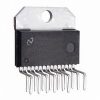
IC AMP AUDIO PWR 25W AB TO220-15
Manufacturer
National Semiconductor
Type
Class ABr
Datasheet
1.LM4731TANOPB.pdf
(16 pages)
Specifications of LM4731TA/NOPB
Output Type
2-Channel (Stereo)
Max Output Power X Channels @ Load
25W x 2 @ 8 Ohm
Voltage - Supply
20 V ~ 56 V, ±10V ~ 28 V
Features
Depop, Mute, Short-Circuit and Thermal Protection
Mounting Type
Through Hole
Package / Case
TO-220-15 (Bent and Staggered Leads)
Lead Free Status / RoHS Status
Lead free / RoHS Compliant
Other names
*LM4731TA
*LM4731TA/NOPB
LM4731TA
*LM4731TA/NOPB
LM4731TA
Available stocks
Company
Part Number
Manufacturer
Quantity
Price
Company:

Part Number:
LM4731TA/NOPB
Manufacturer:
PANASONIC
Quantity:
230


www.national.com
Symbol
Electrical Characteristics
The following specifications apply for V
25˚C.
V
V
Note 1: All voltages are measured with respect to the ground pin, unless otherwise specified.
Note 2: Absolute Maximum Ratings indicate limits beyond which damage to the device may occur. Operating Ratings indicate conditions for which the device is
functional, but do not guarantee specific performance limits. Electrical Characteristics state DC and AC electrical specifications under particular test conditions which
guarantee specific performance limits. This assumes that the device is within the Operating Ratings. Specifications are not guaranteed for parameters where no limit
is given. However, the typical value is a good indication of a device’s performance.
Note 3: The maximum power dissipation must be de-rated at elevated temperatures and is dictated by T
allowable power dissipation is P
and the typical θ
Note 4: Human body model, 100 pF discharged through a 1.5 kΩ resistor.
Note 5: Machine Model: a 220pF - 240pF discharged through all pins.
Note 6: Typical specifications are sepcified at 25˚C and represent the parametric norm.
Note 7: Tested limits are guaranteed to National’s AOQL (Average Outgoing Quality Level).
Note 8: Datasheet min/max specification limits are guaranteed by design, test, or statistical analysis.
Note 9: The operating junction temperature maximum is 150˚C. However, the instantaneous Safe Operating Area temperature is 250˚C.
Note 10: V
differential between V
Note 11: The feedback compensation network limits the bandwidth of the closed-loop response causing the skew rate to be reduced by the high frequency roll-off.
Without feedback compensation the slew rate is typically larger.
Note 12: The LM4731TA package TA15A is a non-isolated package setting the tab of the device and the heat sink to V-potential when the LM4731TA is directly
mounted to the heat sink using only thermal compound. If a mica washer is used in addition to thermal compound, θ
will be electrically isolated from V-.
Bridged Amplifier Application Circuit
IL
IH
-
must have at least -9V at its pin with reference to GND in order for the under-voltage protection circuitry to be disabled. In addition, the voltage
Mute Low Input Voltage
Mute High Input Voltage
JC
is 1.5˚C/W for the TA15A package . Refer to the Thermal Considerations section for more information.
+
and V
Parameter
-
must be greater than 14V.
DMAX
= (T
JMAX
-T
FIGURE 2. Bridged Amplifier Application Circuit
A
+
) / θ
= +22V, V
JC
(Notes 1, 2) (Continued)
or the number given in the Absolute Maximum Ratings, whichever is lower. For the LM4731, T
Not in Mute Mode (Play)
In Mute Mode
-
= −22V and R
Conditions
4
L
= 8Ω unless otherwise specified. Limits apply for T
JMAX
, θ
JC
, and the ambient temperature T
(Note 6)
Typical
CS
2.0
(case to sink) is increased, but the heat sink
LM4731
20060305
(Notes 7, 8)
Limit
0.8
2.5
A
. The maximum
JMAX
(Limits)
V (max)
V (min)
Units
A
= 150˚C
=
Related parts for LM4731TA/NOPB
Image
Part Number
Description
Manufacturer
Datasheet
Request
R

Part Number:
Description:
National Semiconductor [8-Bit D/A Converter]
Manufacturer:
National Semiconductor
Datasheet:
Part Number:
Description:
National Semiconductor [Media Coprocessor]
Manufacturer:
National Semiconductor
Datasheet:
Part Number:
Description:
Digitally Controlled Tone and Volume Circuit with Stereo Audio Power Amplifier, Microphone Preamp Stage and National 3D Sound
Manufacturer:
National Semiconductor
Datasheet:
Part Number:
Description:
Digitally Controlled Tone and Volume Circuit with Stereo Audio Power Amplifier, Microphone Preamp Stage and National 3D Sound
Manufacturer:
National Semiconductor
Datasheet:
Part Number:
Description:
AC97 Rev 2 Codec with Sample Rate Conversion and National 3D Sound
Manufacturer:
National Semiconductor
Part Number:
Description:
Manufacturer:
National Semiconductor
Datasheet:
Part Number:
Description:
Manufacturer:
National Semiconductor
Datasheet:
Part Number:
Description:
General Purpose, Low Voltage, Low Power, Rail-to-Rail Output Operational Amplifiers
Manufacturer:
National Semiconductor
Datasheet:
Part Number:
Description:
8-bit 20 MSPS flash A/D converter.
Manufacturer:
National Semiconductor
Datasheet:
Part Number:
Description:
Low Noise Quad Operational Amplifier
Manufacturer:
National Semiconductor
Datasheet:
Part Number:
Description:
Quad Differential Line Receivers
Manufacturer:
National Semiconductor
Datasheet:
Part Number:
Description:
Quad High Speed Trapezoidal? Bus Transceiver
Manufacturer:
National Semiconductor
Datasheet:
Part Number:
Description:
Dual Line Receiver
Manufacturer:
National Semiconductor
Datasheet:
Part Number:
Description:
TTL to 10k ECL Level Translator with Latch
Manufacturer:
National Semiconductor
Datasheet: