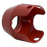
ZBZ1604 Crouzet USA, ZBZ1604 Datasheet - Page 61

ZBZ1604
Manufacturer Part Number
ZBZ1604
Description
17C8378
Manufacturer
Crouzet USA
Datasheet
1.ZBZ1604.pdf
(240 pages)
Specifications of ZBZ1604
Features
Red, Metal
Rohs Compliant
Yes
For Use With
40mm Emergency Stop And Mushroom Head Pushbuttons
- Current page: 61 of 240
- Download datasheet (16Mb)
04/2005
General Tolerances of the Panel and Printed Circuit Board
The cumulative tolerance must not exceed 0.012 inch (0.3 mm): T1 + T2 = 0.012 inch (0.3 mm) maximum.
Related to horizontal direction X
Dimensions:
Connecting Control Units to Printed Circuit Boards (PCB)
Panel cut-out (viewed from installers side)
Printed Circuit Board Drilling
(viewed from electrical block side)
(C1 + 0.71 ±0.004 (18.1 ±0.1)) ±T2
(C2 + 0.71 ±0.004 (18.1 ±0.1)) ±T2
(C3 + 0.71 ±0.004 (18.1 ±0.1)) ±T2
Dual Dimensions inches
Ø2.9 ±0.05
Ø0.11 ±0.002
0.71 ±0.004 (18.1 ±0.1)
mm
A on panel
C + 0.71 inch (18.1 mm) on printed circuit board
Y
a
0.95
24.2
A±T1
0.48
12.1
Push Buttons & Operator Interface - XB4 22 mm Die Cast Chrome Plated
0.16
A1±T1
3
0.47
5.08
4
4
Ø0.88 ±0.004
Ø22.4 ±0.1
0.2
12
A2±T1
Y
= =
= =
(Cn + 0.71 ±0.004 (18.1 ±0.1)) ±T2
An±T1
2
1
0.21
5.4
0.16
Dual Dimensions inches
4
b
0.24
6.1
mm
X
5
0.16
4
X
Related to vertical direction Y
Dimensions:
Installation Precautions:
1. Minimum circuit board thickness:
2. Cut-out diameter:
3. Orientation of body/mounting collar ZB4BZ009:
4. Mounting screw ZBZ006 tightening torque:
5. Allow for pillar ZB4BZ079 and mounting screws
6. The mounting centers marked a and b are
Mounting with adaptor (socket) ZBZ010:
1 Two elongated holes for ZBZ006 screw access.
2 One - 0.09 inch ±0.002 (2.4 mm ±0.05) Ø hole
3 Eight - 0.05 inch (1.2 mm) Ø holes.
4 One - 0.11 inch ±0.002 (2.9 mm ± 0.05)
5 One elongated hole for orientation of printed
© 1999-2005 Schneider Electric All Rights Reserved
Head ZB4B•
0.063 in (1.6 mm)
0.88 in ± 0.004 (22.4 mm ±0.1)
± 2° 30' (excluding a and b)
(0.6 N•m)
every 3.54 inches (90 mm) horizontally (X),
and 4.72 inches (120 mm) vertically (Y).
(for cut-out with 1.18 x 1.52 inch (30 x 40 mm)
centers)
diagonally opposed, in alignment with those on
the printed circuit board marked 4 and 5.
to center ZBZ010 adaptor.
Ø hole, to center printed circuit board
(drilling marked a).
circuit board (drilling marked b).
Panel
ZB4-BZ009
51.45
2.03
ZB4-BZ079
B on panel
D on printed circuit board
ZBE-70•/ZBV-B•7
PCB Layout and Design
53.85
2.12
ZBZ-010
Printed Circuit Board
Dual Dimensions inches
mm
61
Related parts for ZBZ1604
Image
Part Number
Description
Manufacturer
Datasheet
Request
R

Part Number:
Description:
SCREW SOCKET (OT08PC)
Manufacturer:
Crouzet USA
Datasheet:

Part Number:
Description:
PANEL PLATE FOR 813
Manufacturer:
Crouzet USA
Datasheet:

Part Number:
Description:
Controller; CTD46 Dual Display Temperature, 1/16 DIN, NEMA 4X, 110/220VAC
Manufacturer:
Crouzet USA
Datasheet:

Part Number:
Description:
11R1084
Manufacturer:
Crouzet USA
Datasheet:

Part Number:
Description:
11R1086
Manufacturer:
Crouzet USA
Datasheet:

Part Number:
Description:
11R1087
Manufacturer:
Crouzet USA
Datasheet:

Part Number:
Description:
11R1089
Manufacturer:
Crouzet USA
Datasheet:

Part Number:
Description:
11R1078
Manufacturer:
Crouzet USA
Datasheet:

Part Number:
Description:
11R1079
Manufacturer:
Crouzet USA
Datasheet:


