LMV1015UR-15/NOPB National Semiconductor, LMV1015UR-15/NOPB Datasheet - Page 7
LMV1015UR-15/NOPB
Manufacturer Part Number
LMV1015UR-15/NOPB
Description
IC AMP AUDIO MONO AB MIC 4USMD
Manufacturer
National Semiconductor
Type
Class ABr
Datasheet
1.LMV1015UR-25NOPB.pdf
(11 pages)
Specifications of LMV1015UR-15/NOPB
Output Type
1-Channel (Mono)
Voltage - Supply
2 V ~ 5 V
Features
Microphone
Mounting Type
Surface Mount
Package / Case
4-MicroSMD
Operational Class
Class-AB
Audio Amplifier Output Configuration
1-Channel Mono
Audio Amplifier Function
Microphone
Total Harmonic Distortion
0.13@2200Ohm%
Single Supply Voltage (typ)
3V
Dual Supply Voltage (typ)
Not RequiredV
Supply Current (max)
0.3@5VmA
Power Supply Requirement
Single
Rail/rail I/o Type
No
Single Supply Voltage (min)
2V
Single Supply Voltage (max)
5V
Dual Supply Voltage (min)
Not RequiredV
Dual Supply Voltage (max)
Not RequiredV
Operating Temp Range
-40C to 85C
Operating Temperature Classification
Industrial
Mounting
Surface Mount
Pin Count
4
Package Type
uSMD
Lead Free Status / RoHS Status
Lead free / RoHS Compliant
Max Output Power X Channels @ Load
-
Lead Free Status / Rohs Status
Compliant
Other names
LMV1015UR-15
LMV1015UR-15TR
LMV1015UR-15TR


Application Section
HIGH GAIN
The LMV1015 series provides outstanding gain versus the
JFET and still maintains the same ease of implementation,
with improved gain, linearity and temperature stability. A high
gain eliminates the need for extra external components.
BUILT IN GAIN
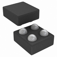
The LMV1015 is offered in 0.3 mm height space saving
small 4-pin micro SMD packages in order to fit inside the
different size ECM canisters of a microphone. The LMV1015
is placed on the PCB inside the microphone using Large
Dome Bump technology (LDB).
The bottom side of the PCB usually shows a bull’s eye
pattern where the outer ring, which is shorted to the metal
can, should be connected to the ground. The center dot on
the PCB is connected to the V
phantom biasing allows both supply voltage and output sig-
nal on one connection.
A-WEIGHTED FILTER
The human ear has a frequency range from 20 Hz to about
20 kHz. Within this range the sensitivity of the human ear is
not equal for each frequency. To approach the hearing re-
sponse weighting filters are introduced. One of those filters
is the A-weighted filter.
The A-weighted filter is usually used in signal to noise ratio
measurements, where sound is compared to device noise.
This filter improves the correlation of the measured data to
the signal to noise ratio perceived by the human ear.
FIGURE 1. Built in Gain
DD
through a resistor. This
20128902
7
MEASURING NOISE AND SNR
The overall noise of the LMV1015 is measured within the
frequency band from 10 Hz to 22 kHz using an A-weighted
filter. The input of the LMV1015 is connected to ground with
a 5 pF capacitor, as in Figure 3. Special precautions in the
internal structure of the LMV1015 have been taken to reduce
the noise on the output.
The signal to noise ratio (SNR) is measured with a 1 kHz
input signal of 18 mV
represents a sound pressure level of 94 dB SPL. No input
capacitor is connected for the measurement.
SOUND PRESSURE LEVEL
The volume of sound applied to a microphone is usually
stated as a pressure level referred to the threshold of hear-
ing of the human ear. The sound pressure level (SPL) in
decibels is defined by:
Sound pressure level (dB) = 20 log P
Where,
P
P
In order to be able to calculate the resulting output voltage of
the microphone for a given SPL, the sound pressure in dB
m
O
is the threshold of hearing (20 µPa)
is the measured sound pressure
FIGURE 3. Noise Measurement Setup
FIGURE 2. A-Weighted Filter
PP
using an A-weighted filter. This
m
/P
O
20128909
www.national.com
20128910
Related parts for LMV1015UR-15/NOPB
Image
Part Number
Description
Manufacturer
Datasheet
Request
R

Part Number:
Description:
IC AMP AUDIO MONO AB MIC 4USMD
Manufacturer:
National Semiconductor
Datasheet:

Part Number:
Description:
Manufacturer:
National Semiconductor
Datasheet:
Part Number:
Description:
Manufacturer:
National Semiconductor
Datasheet:

Part Number:
Description:
Built-in Gain IC�s for High Sensitivity 2-Wire Microphones
Manufacturer:
NSC [National Semiconductor]
Datasheet:
Part Number:
Description:
National Semiconductor [8-Bit D/A Converter]
Manufacturer:
National Semiconductor
Datasheet:
Part Number:
Description:
National Semiconductor [Media Coprocessor]
Manufacturer:
National Semiconductor
Datasheet:
Part Number:
Description:
Digitally Controlled Tone and Volume Circuit with Stereo Audio Power Amplifier, Microphone Preamp Stage and National 3D Sound
Manufacturer:
National Semiconductor
Datasheet:
Part Number:
Description:
Digitally Controlled Tone and Volume Circuit with Stereo Audio Power Amplifier, Microphone Preamp Stage and National 3D Sound
Manufacturer:
National Semiconductor
Datasheet:
Part Number:
Description:
AC97 Rev 2 Codec with Sample Rate Conversion and National 3D Sound
Manufacturer:
National Semiconductor
Part Number:
Description:
Manufacturer:
National Semiconductor
Datasheet:
Part Number:
Description:
Manufacturer:
National Semiconductor
Datasheet:
Part Number:
Description:
General Purpose, Low Voltage, Low Power, Rail-to-Rail Output Operational Amplifiers
Manufacturer:
National Semiconductor
Datasheet:
Part Number:
Description:
8-bit 20 MSPS flash A/D converter.
Manufacturer:
National Semiconductor
Datasheet:
Part Number:
Description:
Low Noise Quad Operational Amplifier
Manufacturer:
National Semiconductor
Datasheet: