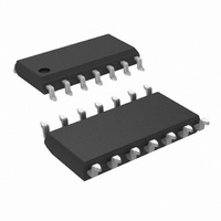
LM1894MX/NOPB National Semiconductor, LM1894MX/NOPB Datasheet - Page 2

LM1894MX/NOPB
Manufacturer Part Number
LM1894MX/NOPB
Description
IC NOISE REDUCT SYS DYNAM 14SOIC
Manufacturer
National Semiconductor
Type
Dynamic Noise Reductionr
Datasheet
1.LM1894MXNOPB.pdf
(12 pages)
Specifications of LM1894MX/NOPB
Applications
Automotive Systems, Players, TV
Mounting Type
Surface Mount
Package / Case
14-SOIC (3.9mm Width), 14-SOL
For Use With
LM1894MTBD - BOARD EVALUATION LM1894
Lead Free Status / RoHS Status
Lead free / RoHS Compliant
Other names
*LM1894MX
*LM1894MX/NOPB
LM1894MX
*LM1894MX/NOPB
LM1894MX
Available stocks
Company
Part Number
Manufacturer
Quantity
Price
Company:
Part Number:
LM1894MX/NOPB
Manufacturer:
MS
Quantity:
6 218
www.national.com
Operating Supply Range
Supply Current
MAIN SIGNAL PATH
Voltage Gain
DC Output Voltage
Channel Balance
Minimum Balance
Maximum Bandwidth
Effective Noise Reduction
Total Harmonic Distortion
Input Headroom
Output Headroom
Signal to Noise
Input Impedance
Channel Separation
Power Supply Rejection
Output DC Shift
CONTROL SIGNAL PATH
Summing Amplifier Voltage Gain
Absolute Maximum Ratings
If Military/Aerospace specified devices are required,
please contact the National Semiconductor Sales Office/
Distributors for availability and specifications.
Electrical Characteristics
V
Supply Voltage
Input Voltage Range, V
Operating Temperature (Note 2)
Storage Temperature
Soldering Information
S
Dual-In-Line Package
= 8V, T
Soldering (10 seconds)
A
= 25˚C, V
Parameter
IN
pk
= 300 mV at 1 kHz, circuit shown in Figure 1 unless otherwise specified
V
DC Ground Pin 9, (Note 3)
DC Ground Pin 9
AC Ground Pin 9 with 0.1 µF
Capacitor, (Note 3)
DC Ground Pin 9, (Note 3)
CCIR/ARM Weighted, (Note 4)
DC Ground Pin 9
Maximum V
AC Ground Pin 9
Maximum V
DC Ground Pin 9
BW = 20 Hz–20 kHz, re 300 mV
CCIR/ARM Weighted re 300 mV
(Note 5)
CCIR Peak, re 300 mV, (Note 6)
Pin 2 and Pin 13
DC Ground Pin 9
C14 = 100 µF,
V
f = 1 kHz
Reference DVM to Pin 14 and
Measuree Output DC Shift from
Minimum to Maximum Band-
width, (Note 7).
Both Channels Driven
−65˚C to +150˚C
S
RIPPLE
AC Ground Pin 9
DC Ground Pin 9
AC Ground Pin 9
DC Ground Pin 9
AC Ground Pin 9
DC Ground Pin 9
= 8V
0˚C to +70˚C
(Note 1)
= 500 mVrms,
IN
OUT
260˚C
Conditions
V
20V
for 3% THD
S
for 3% THD
/2
2
Note 1: “Absolute Maximum Ratings” indicate limits beyond which damage
to the device may occur. Operating Ratings indicate conditions for which the
device is functional, but do not guarantee specific performance limits.
See AN-450 “Surface Mounting Methods and Their Effect
on Product Reliability” for other methods of soldering
surface mount devices.
Small Outline Package
Vapor Phase (60 seconds)
Infrared (15 seconds)
−0.9
−1.0
Min
675
−50
−40
4.5
3.7
0.9
27
82
70
14
V
S
0.05
Typ
965
−10
−70
−56
4.0
1.0
4.0
−1
17
34
79
77
88
76
77
64
20
− 1.5
8
1
1400
−1.1
Max
−14
4.3
1.0
0.1
1.1
18
30
46
26
20
215˚C
Units
220˚C
Vrms
Vp-p
kHz
mA
V/V
mV
V/V
dB
Hz
dB
dB
dB
dB
dB
dB
dB
kΩ
dB
dB
%
V
V


