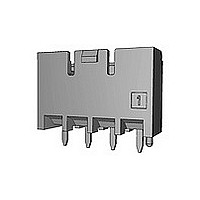
1376421-1 TE Connectivity, 1376421-1 Datasheet - Page 3

1376421-1
Manufacturer Part Number
1376421-1
Description
Manufacturer
TE Connectivity
Specifications of 1376421-1
Product Line
5.0 Power Key Connectors
Product Type
Connector
Connector Type
Header
Pcb Mount Retention
With
Pcb Mount Alignment
Without
Termination Method To Pc Board
Through Hole - Press Fit
Pcb Mounting Orientation
Vertical
Shrouded
Yes
Sealed
No
Shape
Rectangular
Ul File Number
E28476
Csa File Number
LR7189
Mating Post Length (mm [in])
6.30 [0.248]
Mating Retention Type
Latching
Contact - Rated Current (a)
9
Hot Pluggable
No
Operating Voltage Reference
AC
Operating Voltage (vac)
300
Tail Length (mm [in])
3.5 [0.138]
Tail Orientation
In-line
Profile Height (y-axis) (mm [in])
7.00 [0.275]
Number Of Positions
3
Number Of Rows
1
Mating Retention
With
Header Type
Shrouded
Selectively Loaded
No
Pcb Mount Retention Type
Mounting Post/Kinked Legs
Centerline (mm [in])
5.00 [0.197]
Length (x-axis) (mm [in])
16.60 [0.653]
Width (z-axis) (mm [in])
14.10 [0.555]
Contact Type
Pin
Contact Base Material
Copper Alloy
Contact Plating, Mating Area, Material
Tin
Contact Design
Tab
Contact Plating, Mating Area, Thickness (µm [?in])
0.8 [31.5]
Tail Plating Material
Tin
Tail Plating, Thickness (µm [?in])
1 [40]
Connector Style
Receptacle
Housing Color
Natural
Mating Alignment
Without
Housing Material
Nylon 6/6 GF
Ul Flammability Rating
UL 94V-0
Rohs/elv Compliance
RoHS compliant, ELV compliant
Lead Free Solder Processes
Wave solder capable to 240°C, Wave solder capable to 260°C, Wave solder capable to 265°C
Rohs/elv Compliance History
Converted to comply with RoHS directive
Agency/standard
UL, CSA
Ul Rating
Recognized
Ul Voltage Rating (vac)
300
Operating Temperature (°c [°f])
-30 – +105 [-22 – +221]
Applies To
Printed Circuit Board
Pcb Thickness, Recommended (mm [in])
1.60 [0.063]
Application Use
Wire-to-Board
Contact Transmits (typical Application)
Signal (Data)/ Power
Packaging Method
Loose Piece
3.3 定 格
A. 定格電圧
B. 定格電流
C. 使用温度範囲 -30℃~105℃
D. 微小定格
E. 適用プリント基板 板厚 1.6 mm
3.4 性能必要条件と試験方法
製品はFig.3に規定された電気的、機械的、及び耐環境的
性能必要条件に合致するよう設計されていること。試験は
特別に規定されない限り室温下で行われること。
Rev.E
(但し、ヘッダータイン部ランド間を除く、ランド間寸法
3mm以下の場合は150VACを適用)
穴径
タイン用穴 : 1.25±0.05 (パンチ加工穴)
ボス用穴 : 1.3±0.05 (パンチ、ドリル加工穴)
300 VAC
Fig.2参照
1 mV, 1 µA 以上
(但し、温度の上限には、負荷電流によ
って生じる温度上昇分を含む)
極数
Pos.
1.40±0.05 (ドリル加工穴)
4(2row)
6(2row)
電線サイズ
Wire Size
コンタクト
Contact
2
3
4
6
AWG #16
10
9
9
8
8
8
5mm パワー キイ コネクタ
5mm Power Key Connector
Fig. 2
AWG #18
単位 Unit : A
3.3 Ratings :
A. Voltage Rating :
B. Current Rating :
C. Temperature Rating
D. Minimum Rating
E. Applicable P.C.B
3.4 Performance Requirements and Test Descriptions :
The product shall be designed to meet the electrical,
mechanical and environmental performance
requirements specified in Fig.3. All tests shall be
performed in the room temperature unless otherwise
specified.
8
7
7
6
6
6
Diameter of Thehole :
For Tine :
For Boss : 1.3±0.05(Punched Hole & Drilled Hole)
リセ ・ コンタクト :
タブ ・ コンタクト :
Rec. Contact :
Tab Contact :
AWG #20
7
6
6
5
5
5
1.25±0.05 (Punched Hole)
1.40±0.05 (Drilled Hole)
300VAC(Except for the distance
among round of PCB. When
the distance among the round is
3mm or less,it is accepted
150VAC.)
See Fig. 2
AWG #22
: -30℃ to 105℃
(Include temperature rising
by energized current)
:
:
5
4
4
3
3
2
1mV, 1µA Minimum
Thickness : 1.6 mm
108-5699
AWG #24
3 of 19
3
2
2
2
2
2


