1376421-1 TE Connectivity, 1376421-1 Datasheet - Page 4
1376421-1
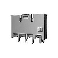
Manufacturer Part Number
1376421-1
Description
Manufacturer
TE Connectivity
Specifications of 1376421-1
Product Line
5.0 Power Key Connectors
Product Type
Connector
Connector Type
Header
Pcb Mount Retention
With
Pcb Mount Alignment
Without
Termination Method To Pc Board
Through Hole - Press Fit
Pcb Mounting Orientation
Vertical
Shrouded
Yes
Sealed
No
Shape
Rectangular
Ul File Number
E28476
Csa File Number
LR7189
Mating Post Length (mm [in])
6.30 [0.248]
Mating Retention Type
Latching
Contact - Rated Current (a)
9
Hot Pluggable
No
Operating Voltage Reference
AC
Operating Voltage (vac)
300
Tail Length (mm [in])
3.5 [0.138]
Tail Orientation
In-line
Profile Height (y-axis) (mm [in])
7.00 [0.275]
Number Of Positions
3
Number Of Rows
1
Mating Retention
With
Header Type
Shrouded
Selectively Loaded
No
Pcb Mount Retention Type
Mounting Post/Kinked Legs
Centerline (mm [in])
5.00 [0.197]
Length (x-axis) (mm [in])
16.60 [0.653]
Width (z-axis) (mm [in])
14.10 [0.555]
Contact Type
Pin
Contact Base Material
Copper Alloy
Contact Plating, Mating Area, Material
Tin
Contact Design
Tab
Contact Plating, Mating Area, Thickness (µm [?in])
0.8 [31.5]
Tail Plating Material
Tin
Tail Plating, Thickness (µm [?in])
1 [40]
Connector Style
Receptacle
Housing Color
Natural
Mating Alignment
Without
Housing Material
Nylon 6/6 GF
Ul Flammability Rating
UL 94V-0
Rohs/elv Compliance
RoHS compliant, ELV compliant
Lead Free Solder Processes
Wave solder capable to 240°C, Wave solder capable to 260°C, Wave solder capable to 265°C
Rohs/elv Compliance History
Converted to comply with RoHS directive
Agency/standard
UL, CSA
Ul Rating
Recognized
Ul Voltage Rating (vac)
300
Operating Temperature (°c [°f])
-30 – +105 [-22 – +221]
Applies To
Printed Circuit Board
Pcb Thickness, Recommended (mm [in])
1.60 [0.063]
Application Use
Wire-to-Board
Contact Transmits (typical Application)
Signal (Data)/ Power
Packaging Method
Loose Piece


3.5
4 of 19
Requirements
Requirements
Requirement
Procedures
Procedures
Procedures
Test Items
Test Items
Test Items
試験項目
試験方法
試験項目
試験方法
試験項目
試験方法
規格値
規格値
規格値
項番
項番
項番
性能必要条件と試験方法の要約
No.
No.
No.
s
製品の確認
製品図面とTE 取付適用規格
114-5292 の必要条件に合致していること。
各試験後は、性能に影響する様な腐蝕なき
こと。
目視により、コネクタの機能上支障を
きたす損傷を検査する。
総合抵抗(ローレベル)
10 m
20 m
ハウジングに組み込まれ嵌合したコンタクト
を開路電圧20mV以下、閉路電流10mA以
下の条件で測定する。
但し、電線の抵抗分は差し引く。
Fig. 7 参照。
EIA 364-23
絶縁抵抗
1000 M
500 M
500 V DC 印加。
コネクタ嵌合した状態で隣接コンタクト間
及びコンタクトとハウジングの外郭の間で
測定。
MIL-STD-202, 試験法 301 条件 B
EIA 364-21
以下 (初期)
以下 (終期)
以上 (終期)
以上 (初期)
電 気 的 性 能
Fig. 3 (続く) (To be continued)
5mm パワー キイ コネクタ
5mm Power Key Connector
Electrical Requirements
3.5.1
3.5.2
3.5.3
Examination of Product
Meets requirements of product drawing and
TE
Specification (114-5292)
After
performance.
Visual inspection
No physical damage
3.5 Test Requirements and Procedures Summary :
Termination Resistance (Low Level)
10 m Max. (Initial)
20 m Max. (Final)
Subject mated contacts assembled in
housing to 20mV Max. open circuit at 10mA.
Take the resistance of the wire only away
from measurement
Fig. 7.
EIA 364-23
Insulation Resistance
1000 M Min. (Initial)
500 M Min. (Final)
Impressed voltage 500 V DC.
Test between adjacent circuits and between
the
surface of housing and contact of mated
connectors.
MIL-STD-202, Method 301 Condition B
EIA 364-21
test,
no
corrosion
influence
108-5699
Rev. E
Related parts for 1376421-1
Image
Part Number
Description
Manufacturer
Datasheet
Request
R

Part Number:
Description:
Printers THERMAL PRINTER HS-SLEEVE MARKER
Manufacturer:
TE Connectivity


Part Number:
Description:
Manufacturer:
TE Connectivity
Datasheet:


Part Number:
Description:
Manufacturer:
TE Connectivity
Datasheet:

Part Number:
Description:
Manufacturer:
TE Connectivity
Datasheet: