1376421-1 TE Connectivity, 1376421-1 Datasheet - Page 6
1376421-1
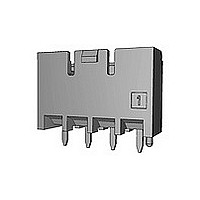
Manufacturer Part Number
1376421-1
Description
Manufacturer
TE Connectivity
Specifications of 1376421-1
Product Line
5.0 Power Key Connectors
Product Type
Connector
Connector Type
Header
Pcb Mount Retention
With
Pcb Mount Alignment
Without
Termination Method To Pc Board
Through Hole - Press Fit
Pcb Mounting Orientation
Vertical
Shrouded
Yes
Sealed
No
Shape
Rectangular
Ul File Number
E28476
Csa File Number
LR7189
Mating Post Length (mm [in])
6.30 [0.248]
Mating Retention Type
Latching
Contact - Rated Current (a)
9
Hot Pluggable
No
Operating Voltage Reference
AC
Operating Voltage (vac)
300
Tail Length (mm [in])
3.5 [0.138]
Tail Orientation
In-line
Profile Height (y-axis) (mm [in])
7.00 [0.275]
Number Of Positions
3
Number Of Rows
1
Mating Retention
With
Header Type
Shrouded
Selectively Loaded
No
Pcb Mount Retention Type
Mounting Post/Kinked Legs
Centerline (mm [in])
5.00 [0.197]
Length (x-axis) (mm [in])
16.60 [0.653]
Width (z-axis) (mm [in])
14.10 [0.555]
Contact Type
Pin
Contact Base Material
Copper Alloy
Contact Plating, Mating Area, Material
Tin
Contact Design
Tab
Contact Plating, Mating Area, Thickness (µm [?in])
0.8 [31.5]
Tail Plating Material
Tin
Tail Plating, Thickness (µm [?in])
1 [40]
Connector Style
Receptacle
Housing Color
Natural
Mating Alignment
Without
Housing Material
Nylon 6/6 GF
Ul Flammability Rating
UL 94V-0
Rohs/elv Compliance
RoHS compliant, ELV compliant
Lead Free Solder Processes
Wave solder capable to 240°C, Wave solder capable to 260°C, Wave solder capable to 265°C
Rohs/elv Compliance History
Converted to comply with RoHS directive
Agency/standard
UL, CSA
Ul Rating
Recognized
Ul Voltage Rating (vac)
300
Operating Temperature (°c [°f])
-30 – +105 [-22 – +221]
Applies To
Printed Circuit Board
Pcb Thickness, Recommended (mm [in])
1.60 [0.063]
Application Use
Wire-to-Board
Contact Transmits (typical Application)
Signal (Data)/ Power
Packaging Method
Loose Piece


6 of 19
Requirements
Requirements
Requirements
Procedures
Procedures
Test Items
Test Items
試験項目
試験方法
試験項目
試験方法
規格値
規格値
規格値
項番
項番
No.
No.
振動(低周波)
振動中 1 µsec. をこえる不連続導通を
生じないこと。
20m 以下 (終期)
振動中 1 µsec. をこえる不連続導通を
生じないこと。
20m 以下 (終期)
嵌合したコネクタに1.52mmの振幅で、
10-55-10Hzに毎分1サイクルの割合で
変化する掃引振動を直交する
三方向軸に各2時間ずつ与えること。
100 mA を通電。 Fig. 8 参照
MIL-STD-202, 試験法 201A
EIA 364-28
衝撃
衝撃により1µ sec. をこえる不連続導通を
生じないこと。
20 m
嵌合したコネクタ (50 G)
衝撃パルス波型 : 半波正弦波形
持続時間
衝撃回数
Fig. 8 参照
MIL-STD-202, 試験法 213 条件 A
EIA 364-27
以下 (終期)
:
:
機 械 的 性 能
11 msec.
X, Y, Z 軸正逆方向に
各3 回宛、 合計18回
Fig. 3 (続く) (To be Continued)
5mm パワー キイ コネクタ
5mm Power Key Connector
Mechanical Requirements
3.5.6
3.5.7
Vibration (Low Frequency)
No electrical discontinuity greater than
1 µsec. shall occur.
20 m Max. (Final)
No electrical discontinuity greater than
1 µsec. shall occur.
20 m Max. (Final)
Subject mated connectors to 10-55-10 Hz
traversed in 1 minute at 1.52mm amplitude 2
hours each of 3 mutually perpendicular
planes.
100 mA applied. Fig. 8
MIL-STD-202, Method 201A
EIA 364-28
Physical Shock
No electrical discontinuity greater than
1µ sec. shall occur.
20 m Max. (Final)
Mated Conn. (50 G)
Waveform
Duration
Number of Drops
and reversed directions of X, Y and Z axes,
totally 18 drops.
See Fig. 8
MIL-STD-202, Method 213 Condition A
EIA 364-27
: Halfsign Curve
: 11 m sec.
: 3 drops each to normal
108-5699
Rev. E
Related parts for 1376421-1
Image
Part Number
Description
Manufacturer
Datasheet
Request
R

Part Number:
Description:
Printers THERMAL PRINTER HS-SLEEVE MARKER
Manufacturer:
TE Connectivity


Part Number:
Description:
Manufacturer:
TE Connectivity
Datasheet:


Part Number:
Description:
Manufacturer:
TE Connectivity
Datasheet:

Part Number:
Description:
Manufacturer:
TE Connectivity
Datasheet: