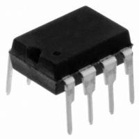
11LC160-I/P Microchip Technology, 11LC160-I/P Datasheet - Page 12

11LC160-I/P
Manufacturer Part Number
11LC160-I/P
Description
IC EEPROM 16KBIT 100KHZ 8DIP
Manufacturer
Microchip Technology
Datasheets
1.11LC010T-ITT.pdf
(44 pages)
2.11LC010T-ITT.pdf
(22 pages)
3.11LC010T-ITT.pdf
(6 pages)
4.11LC160T-ITT.pdf
(38 pages)
Specifications of 11LC160-I/P
Memory Size
16K (2K x 8)
Package / Case
8-DIP (0.300", 7.62mm)
Operating Temperature
-40°C ~ 85°C
Format - Memory
EEPROMs - Serial
Memory Type
EEPROM
Speed
100kHz
Interface
UNI/O™ (Single Wire)
Voltage - Supply
2.5 V ~ 5.5 V
Organization
2048 x 8
Interface Type
Serial
Maximum Clock Frequency
100 KHz
Supply Voltage (max)
5.5 V
Supply Voltage (min)
2.5 V
Maximum Operating Current
50 uA
Maximum Operating Temperature
+ 85 C
Mounting Style
Through Hole
Minimum Operating Temperature
- 40 C
Operating Supply Voltage
3.3 V, 5 V
Lead Free Status / RoHS Status
Lead free / RoHS Compliant
Lead Free Status / RoHS Status
Lead free / RoHS Compliant, Lead free / RoHS Compliant
UNI/O
6.0
All operations must be preceded by a start header.
The start header consists of holding SCIO low for a
period of T
‘
the slave’s internal clock period with the master’s clock
period, so accurate timing is very important. An
Acknowledge sequence is then performed following
transmission of the start header. Figure 6-1 shows an
example of the start header sequence.
FIGURE 6-1:
During the Acknowledge sequence following the start
header, no slave device will respond with a SAK.
Within this time, the bus will not be driven by any
device and no edge transition will occur. Refer to
Section 5.1 “Acknowledge Sequence” for details.
6.1
6.1.1
In order to provide an accurate time base with which to
extract the serial clock frequency, an oscillator must be
used by each slave device on the bus. This can be
either internal or external to the device, though includ-
ing an internal oscillator is strongly recommended to
avoid requiring excess external components.
The necessary accuracy of the oscillator to a specific
frequency is dependent only on the design of the
device. The only bus-based requirements are that the
chosen oscillator be stable enough across voltage and
temperature and that the frequency is high enough to
provide a reasonable state of synchronization during a
command.
If an internal oscillator is included, it is recommended
that it be powered down during Idle and Standby
modes so as to reduce unnecessary power consump-
tion. The T
such an internal oscillator can power-up and stabilize.
DS22076D-page 12
01010101
SCIO
START HEADER
Synchronization
HDR
OSCILLATOR
T
’ code. This code is used to synchronize
HDR
SS
®
, followed by transmitting an 8-bit
period provides a time during which
T
Bus
HDR
START HEADER EXAMPLE
‘0’
‘1’
‘0’
Synchronization
‘1’
When a standby pulse is not required (i.e., between
successive commands to the same device), a period
of T
and before the beginning of the start header.
6.1.2
The start header is utilized by slave devices as a
means of determining the bit period used by the mas-
ter. During the start header, a counter can be used to
measure the amount of time required to transmit 8 bits
of data. This counter can then be divided down to
determine the bit period, T
comparison for all other bits.
The required widths of such counters are dependent
upon the oscillator frequency used and would need to
be wide enough to support 100 µs bit periods (10 kbps
operation).
6.2
During communication, it is possible that either the
master’s or the slave’s reference clock may drift. This
may be due to many events, including changes in volt-
age or temperature. If not corrected for, such a drift will
eventually cause a loss of synchronization. Therefore,
all slave devices must monitor the middle edge of
each MAK bit and where it occurs relative to the
slave’s bit period, and then adjust its frequency to
match.
6.2.1
During every MAK bit, the middle edge should also be
used to reset the slave’s phase (i.e., the slave should
assume that the MAK edge is located at the middle of
the master’s bit period and therefore use it as a
reference for further communication).
This will ensure that any error in phase which may
occur will not accumulate from byte to byte.
‘0’
SS
must be observed after the end of the command
Re-synchronization
‘1’
SERIAL FREQUENCY EXTRACTION
PHASE ADJUSTMENT
‘0’
© 2009 Microchip Technology Inc.
E
‘1’
, which can be used as a
MAK
NoSAK


