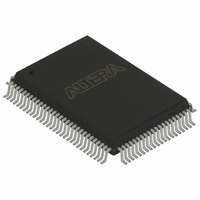
EPC16QC100 Altera, EPC16QC100 Datasheet - Page 30

EPC16QC100
Manufacturer Part Number
EPC16QC100
Description
IC CONFIG DEVICE 16MBIT 100-PQFP
Manufacturer
Altera
Series
EPCr
Datasheet
1.EPC8QC100.pdf
(34 pages)
Specifications of EPC16QC100
Programmable Type
In System Programmable
Memory Size
16Mb
Voltage - Supply
3 V ~ 3.6 V
Operating Temperature
0°C ~ 70°C
Package / Case
100-MQFP, 100-PQFP
Lead Free Status / RoHS Status
Contains lead / RoHS non-compliant
Other names
544-1226
Available stocks
Company
Part Number
Manufacturer
Quantity
Price
Company:
Part Number:
EPC16QC100
Manufacturer:
ALTERA
Quantity:
1 045
Part Number:
EPC16QC100
Manufacturer:
ALTERA/阿尔特拉
Quantity:
20 000
Company:
Part Number:
EPC16QC100N
Manufacturer:
ALTERA30
Quantity:
660
Part Number:
EPC16QC100N
Manufacturer:
ALTERA/阿尔特拉
Quantity:
20 000
Company:
Part Number:
EPC16QC100T
Manufacturer:
ROHM
Quantity:
233
1–30
Table 1–14. Enhanced Configuration Device Configuration Parameters (Part 2 of 2)
Operating Conditions
Table 1–15. Enhanced Configuration Device Absolute Maximum Rating
Table 1–16. Enhanced Configuration Device Recommended Operating Conditions
Configuration Handbook (Complete Two-Volume Set)
t
f
t
t
t
t
t
t
Notes to
(1) To calculate t
(2) This parameter is used for CRC error detection by the FPGA.
(3) This parameter is used for CONF_DONE error detection by the enhanced configuration device.
(4) The FPGA V
V
V
I
I
P
T
T
T
V
V
V
T
T
T
LOE
ECLK
ECLK
ECLKH
ECLKL
ECLKR
ECLKF
POR
MAX
OUT
AMB
A
STG
J
R
F
CC
I
D
CC
I
O
Symbol
Symbol
(4)
Symbol
Table
1–14:
CCINT
Supplies voltage for 3.3-V operation
Input voltage
Output voltage
Operating temperature
Input rise time
Input fall time
OH
, use the following equation: t
OE assert time to assure reset
EXCLK input frequency
EXCLK input period
EXCLK input duty cycle high time
EXCLK input duty cycle low time
EXCLK input rise time
EXCLK input fall time
POR time
ramp time should be less than 1-ms for 2-ms POR, and it should be less than 70 ms for 100-ms POR.
Table 1–15
recommended operating conditions, DC operating conditions, supply current values,
and pin capacitance data for the enhanced configuration devices.
Supply voltage
DC input voltage
DC V
DC output current, per pin
Power dissipation
Storage temperature
Ambient temperature
Junction temperature
CC
Parameter
or ground current
Parameter
Parameter
through
OH
= 0.5 (DCLK period) - 2.5 ns.
Table 1–19
Chapter 1: Enhanced Configuration Devices (EPC4, EPC8, and EPC16) Data Sheet
With respect to ground
With respect to ground
With respect to ground
provide information about absolute maximum ratings,
For commercial use
For industrial use
40% duty cycle
40% duty cycle
40% duty cycle
Under bias
Under bias
Condition
Condition
100 MHz
100 MHz
Condition
100 ms
No bias
2 ms
—
—
—
—
—
—
—
—
—
Min
60
—
10
—
—
70
4
4
1
–0.3
Min
–40
3.0
—
—
-0.2
-0.5
Min
-25
-65
-65
0
0
—
—
—
© December 2009 Altera Corporation
100
Typ
—
—
—
—
—
—
—
2
V
CC
Max
V
Max
3.6
100
150
135
135
360
70
85
20
20
4.6
3.6
25
+ 0.3
CC
Max
100
120
Operating Conditions
—
—
—
—
3
3
3
Unit
mW
Unit
mA
mA
ns
ns
MHz
Unit
V
V
C
C
C
V
V
V
C
C
ms
ms
ns
ns
ns
ns
ns
ns


