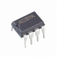
EPC1441PC8 Altera, EPC1441PC8 Datasheet - Page 23

EPC1441PC8
Manufacturer Part Number
EPC1441PC8
Description
IC CONFIG DEVICE 400KBIT 8-DIP
Manufacturer
Altera
Series
EPCr
Datasheet
1.EPC1PC8.pdf
(26 pages)
Specifications of EPC1441PC8
Programmable Type
OTP
Memory Size
440kb
Voltage - Supply
3 V ~ 3.6 V, 4.75 V ~ 5.25 V
Operating Temperature
0°C ~ 70°C
Package / Case
8-DIP (0.300", 7.62mm)
Memory Type
Flash
Clock Frequency
8MHz
Supply Voltage Range
3V To 5.25V
Memory Case Style
DIP
No. Of Pins
8
Operating Temperature Range
0°C To +70°C
Termination Type
DIP
Rohs Compliant
No
Filter Terminals
DIP
For Use With
PLMJ1213 - PROGRAMMER ADAPTER 20 PIN J-LEAD
Lead Free Status / RoHS Status
Contains lead / RoHS non-compliant
Other names
544-1224-5
Available stocks
Company
Part Number
Manufacturer
Quantity
Price
Company:
Part Number:
EPC1441PC8
Manufacturer:
ALIERA
Quantity:
25
Company:
Part Number:
EPC1441PC8
Manufacturer:
ALTERA
Quantity:
5 510
Company:
Part Number:
EPC1441PC8
Manufacturer:
ALTERA92
Quantity:
618
Part Number:
EPC1441PC8
Manufacturer:
ALTERA/阿尔特拉
Quantity:
20 000
Chapter 4: Configuration Devices for SRAM-Based LUT Devices Data Sheet
Pin Information
Table 4–20. EPC1, EPC2 and EPC1441 Pin Functions During Configuration (Part 3 of 3)
© December 2009
TMS
TCK
VCCSEL
VPPSEL
VPP
VCC
GND
Notes to
(1) This package is available for EPC1 and EPC1441 devices only.
(2) This package is available for EPC2 and EPC1441 devices only.
Pin Name
Table
4–20:
Altera Corporation
PDIP
8-Pin
7, 8
N/A
N/A
N/A
N/A
N/A
5
(1)
Pin Number
20-Pin
PLCC
19
14
18
20
10
3
5
TQFP
32-Pin
25
32
17
23
27
12
3
(2)
Input
Input
Input
Input
Power
Power
Ground
Pin Type
JTAG mode select pin. Connect this pin to V
JTAG circuitry is not used.
This pin is only available in EPC2 devices.
JTAG clock pin. Connect this pin to ground if the
JTAG circuitry is not used.
This pin is only available in EPC2 devices.
Mode select for V
connected to ground if the device uses a 5.0-V power
supply (V
V
3.3 V).
This pin is only available in EPC2 devices.
Mode select for V
ground if V
(V
V
This pin is only available in EPC2 devices.
Programming power pin. For the EPC2 device, this
pin is normally tied to V
V
programming times. For EPC1 and EPC1441 devices,
V
This pin is only available in EPC2 devices.
Power pin.
Ground pin. A 0.2-µF decoupling capacitor must be
placed between the VCC and GND pins.
CC
PP
PP
PP
PP
if the device uses a 3.3-V power supply (V
uses a 3.3-V power supply (V
can be tied to 5.0 V to improve in-system
must be tied to V
= 5.0 V). VPPSEL must be connected to V
Configuration Handbook (Complete Two-Volume Set)
CC
PP
= 5.0 V). VCCSEL must be connected to
uses a 5.0-V power supply
CC
PP
. VPPSEL must be connected to
supply. VCCSEL must be
Description
CC
.
CC
. If the EPC2 V
PP
= 3.3 V).
CC
is 3.3 V,
CC
CC
if the
CC
=
4–23
if


