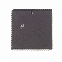
DP8421AV-25 National Semiconductor, DP8421AV-25 Datasheet - Page 17

DP8421AV-25
Manufacturer Part Number
DP8421AV-25
Description
IC CTRLR/DVR CMOS PROGRAM 68PLCC
Manufacturer
National Semiconductor
Datasheet
1.DP8420AV-25.pdf
(58 pages)
Specifications of DP8421AV-25
Controller Type
Dynamic RAM (DRAM)
Voltage - Supply
4.5 V ~ 5.5 V
Operating Temperature
0°C ~ 70°C
Package / Case
68-PLCC
Lead Free Status / RoHS Status
Contains lead / RoHS non-compliant
Other names
*DP8421AV-25
Available stocks
Company
Part Number
Manufacturer
Quantity
Price
Company:
Part Number:
DP8421AV-25
Manufacturer:
Texas Instruments
Quantity:
10 000
Part Number:
DP8421AV-25
Manufacturer:
NS/国半
Quantity:
20 000
4 0 Port A Access Modes
4 5 ADDITIONAL ACCESS SUPPORT FEATURES
To support the different modes of accessing
DP8420A 21A 22A offer other access features These ad-
ditional features include Address Latches and Column In-
crement (for page burst mode support) Address Pipelining
and Delay CAS (to allow the user with a multiplexed bus to
ensure valid data is present before CAS is asserted)
4 5 1 Address Latches and Column Increment
The Address Latches can be programmed through pro-
gramming bit B0 They can be programmed to either latch
the address or remain in a fall-through mode If the address
latches are used to latch the address the controller will
function as follows
In Mode 0 the rising edge of ALE places the latches in fall-
through once ALE is negated the address present in the
row column and bank input is latched
The address latches function differently with the DP8422A
The DP8422A will latch the address of the currently granted
port If Port A is currently granted the address will be
latched as described in Section 4 5 1 If Port A is not grant-
ed and requests an access the address will be latched on
the first or second positive edge of CLK after GRANTB has
been negated depending on the programming bits R0 R1
(Continued)
FIGURE 10 Column Increment
the
17
In Mode 1 the address latches are in fall through mode until
ADS is asserted ADS asserted latches the address
Once the address is latched the column address can be
incremented with the input COLINC COLINC can be used
for sequential accesses of static column DRAMs COLINC
can also be used with the ECAS inputs to support sequen-
tial accesses to page mode DRAMs as shown in Figure 10
COLINC should only be asserted when the signal RFIP is
negated during an access since this input functions as ex-
tended refresh when RFIP is asserted COLINC must be
negated (0) when the address is being latched (ADS falling
edge in Mode 1) If COLINC is asserted with all of the bits of
the column address asserted (ones) the column address
will return to zero
For Port B if GRANTB is asserted the address will be
latched with AREQB asserted If GRANTB is negated the
address will latch on the first or second positive edge of
CLK after GRANTB is asserted depending on the program-
ming bits R0 R1
TL F 8588 – C4


