LNK500PN Power Integrations, LNK500PN Datasheet - Page 8
LNK500PN
Manufacturer Part Number
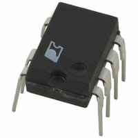
LNK500PN
Description
IC SWIT OCP CV/CC HV 8DIP
Manufacturer
Power Integrations
Series
LinkSwitch®r
Datasheet
1.LNK500PN.pdf
(20 pages)
Specifications of LNK500PN
Output Isolation
Isolated
Frequency Range
24 ~ 49.5kHz
Voltage - Output
700V
Power (watts)
4W
Operating Temperature
-40°C ~ 150°C
Package / Case
8-DIP (0.300", 7.62mm), 7 Leads
Output Voltage
5.6 V
Input / Supply Voltage (max)
265 VAC
Input / Supply Voltage (min)
85 VAC
Duty Cycle (max)
80 %
Switching Frequency
42 KHz
Supply Current
1.06 mA
Operating Temperature Range
- 40 C to + 150 C
Mounting Style
Through Hole
For Use With
596-1001 - KIT DESIGN ACCELERATOR ADAPTER
Lead Free Status / RoHS Status
Lead free / RoHS Compliant
Other names
596-1029-5
Available stocks
Company
Part Number
Manufacturer
Quantity
Price

Part Number:
LNK500PN
Manufacturer:
POWER
Quantity:
20 000


To aid the designer, the power table reflects these differences. For
CV/CC designs the typical power column and for CV designs
the minimum power column should be used, respectively.
Additionally, figures are based on the following conditions:
1. The minimum DC input bus voltage is 90 V or higher. This
2. Design is a discontinuous mode flyback converter.
3. A secondary output of 5 V with a Schottky rectifier diode.
4. Assumed efficiency of 70%.
5. The part is board mounted with SOURCE pins soldered to
6. An output cable with a total resistance of 0.2 Ω.
In addition to the thermal environment (sealed enclosure,
ventilated, open frame, etc), the maximum power capability
of LinkSwitch in a given application depends on transformer
core size, efficiency, primary inductance tolerance, minimum
specified input voltage, input storage capacitance, output voltage,
output diode forward drop, etc., and can be different from the
values shown in Table 1.
Transformer Design
To provide an approximately CV/CC output, the transformer
should be designed to be discontinuous; all the energy stored
in the transformer is transferred to the secondary during the
MOSFET off time. Energy transfer in discontinuous mode is
independent of line voltage.
The peak power point prior to entering constant current operation
is defined by the maximum power transferred by the transformer.
The power transferred is given by the expression P = 0.5·L
where L
squared and f is the switching frequency.
To simplify analysis, the data sheet parameter table specifies an
I
switching frequency normalized to the feedback parameter I
This provides a single term that specifies the variation of the
peak power point in the power supply due to LinkSwitch.
2
f coefficient. This is the product of current limit squared and
8
corresponds to a filter capacitor of 3 µF/W for universal input
and 1 µF/W for 230 VAC or 115 VAC input with doubler
input stage.
Continuous mode designs can result in loop instability and
are therefore not recommended. For typical output power
figures, nominal values for primary inductance and I
assumed. For minimum output power figures, primary
inductance minus 10% and the minimum I
assumed. For no-load consumption <300 mW, a V
range 40 V to 60 V is assumed. For no-load consumption
<500 mW and higher output power capability, a V
range 60 V to
sufficient area of copper to keep the die temperature at or
below 100 °C.
LNK500
D
2/05
P
is the primary inductance, I
100 V is assumed.
2
is the primary peak current
2
f value are
OR
OR
in the
in the
2
P
f are
·I
DCT
2
·f,
.
As primary inductance tolerance is part of the expression
that determines the peak output power point (start of the CC
characteristic) this parameter should be well controlled. For
an estimated overall constant current tolerance of ±25% the
primary inductance tolerance should be ±10% or better. This
is achievable using standard low cost, center leg gapping
techniques where the gap size is typically 0.08 mm or larger.
Smaller gap sizes are possible but require non-standard, tighter
ferrite A
Other gapping techniques such as film gapping allow tighter
tolerances (±7% or better) with associated improvements in
the tolerance of the peak power point. Please consult your
transformer vendor for guidance.
Core gaps should be uniform. Uneven core gapping, especially
with small gap sizes, may cause variation in the primary
inductance with flux density (partial saturation) and make the
constant current region non-linear. To verify uniform gapping
it is recommended that the primary current wave-shape be
examined while feeding the supply from a DC source. The
gradient is defined as di/dt = V/L and should remain constant
throughout the MOSFET on time. Any change in gradient of
the current ramp is an indication of uneven gapping.
Measurements made using an LCR bridge should not be solely
relied upon; typically these instruments only measure at currents
of a few milliamps. This is insufficient to generate high enough
flux densities in the core to show uneven gapping.
For a typical EE13 core using center leg gapping, a 0.08 mm
gap (A
±10% to be maintained in standard high volume production.
This allows the EE13 to be used in designs up to 2.75 W with
less than 300 mW no-load consumption. If film gapping is used
then this increases to 3 W. Moving to a larger core, EE16 for
example, allows a 3 W output with center leg gapping.
The transformer turns ratio should be selected to give a V
(output voltage reflected through secondary to primary turns
ratio) of 40 V to 60 V. In designs not required to meet 300 mW
no-load consumption targets, the transformer can be designed
with higher V
maintained. This increases the output power capability. For
example, a 230 VAC input design using an EE19 transformer
core with V
output power. Note: the linearity of the CC region of the power
supply output characteristic is influenced by V
important aspect of the application, the output characteristic
should be checked before finalizing the design.
Output Characteristic Variation
Both the device tolerance and external circuit govern the overall
tolerance of the LinkSwitch output characteristic. Estimated
peak power point tolerances for a 3 W design are ±10% for
LG
L
of 190 nH/t
tolerances.
OR
>70 V, is capable of delivering up to 5.5 W typical
OR
as long as discontinuous mode operation is
2
) allows a primary inductance tolerance of
OR
. If this is an
OR
Related parts for LNK500PN
Image
Part Number
Description
Manufacturer
Datasheet
Request
R

Part Number:
Description:
Energy Ef?cient, Cv Or Cv/cc Switcher For Very Low Cost Adapters And Chargers
Manufacturer:
Power Integrations, Inc.
Datasheet:

Part Number:
Description:
SOP-16
Manufacturer:
Power Integrations
Datasheet:
Part Number:
Description:
DIP8
Manufacturer:
Power Integrations
Datasheet:
Part Number:
Description:
TO-263
Manufacturer:
Power Integrations
Datasheet:
Part Number:
Description:
TO-263
Manufacturer:
Power Integrations
Datasheet: