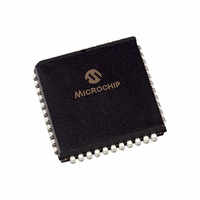
TC820CLW Microchip Technology, TC820CLW Datasheet - Page 15

TC820CLW
Manufacturer Part Number
TC820CLW
Description
IC ADC 3 3/4DGT LGC PROBE 44PLCC
Manufacturer
Microchip Technology
Datasheet
1.TC820CPL.pdf
(34 pages)
Specifications of TC820CLW
Display Type
LCD
Configuration
7 Segment + 2 Annunciators
Digits Or Characters
A/D 3.75 Digits
Current - Supply
1mA
Voltage - Supply
9V
Operating Temperature
0°C ~ 70°C
Mounting Type
Surface Mount
Package / Case
44-PLCC
Lead Free Status / RoHS Status
Lead free / RoHS Compliant
Interface
-
Available stocks
Company
Part Number
Manufacturer
Quantity
Price
Company:
Part Number:
TC820CLW
Manufacturer:
Microchip Technology
Quantity:
10 000
Company:
Part Number:
TC820CLW713
Manufacturer:
Microchip Technology
Quantity:
10 000
4.0
4.1
The TC820 Operating modes are selected with the
function control inputs. See the control input truth,
Table
the low logic level is ≤ DGND +1.5V.
TABLE 4-1:
4.1.1
This input determines whether the TC820 is in the
Analog-to-Digital
Frequency Counter mode. When FREQ/VOLTS is
connected to V
at the RANGE/FREQ input. When unconnected, or
connected to DGND, the TC820 will operate as an
analog-to-digital converter. This input has an internal
5 µA pull-down to DGND.
4.1.2
The LOGIC input is used to activate the logic probe
function. When connected to V
the Logic Probe mode. The LCD will show "OL" and all
decimal points will be off. The decimal point inputs
directly control "high" and "low" display annunciators.
When LOGIC is unconnected, or connected to DGND,
the TC820 will perform analog-to-digital or frequency
measurements, as selected by the FREQ/VOLTS
input. The LOGIC input has an internal 5 µA pull-down
to DGND.
4.1.3
The function of this dual purpose pin is determined by
the FREQ/VOLTS input. When FREQ/VOLTS is
connected to V
frequency counter function. Pulses at this input are
counted with a time-base equal to F
this input has CMOS input levels (V
DGND +1.5V), an external buffer is recommended.
© 2007 Microchip Technology Inc.
Note 1:
VOLTS
FREQ/
X
0
0
1
4-1. The high logic threshold is ≥ V
2:
FUNCTION CONTROL INPUTS
PIN
Functional Description
Logic Input
Frequency
RANGE/
Counter
FREQ
Logic "0" = DGND
Logic "1" = V
FREQ/VOLTS
LOGIC
RANGE/FREQ
Input
X
0
1
DD
DD
, the TC820 will measure frequency
TC820 CONTROL INPUT
TRUTH TABLE
, RANGE/FREQ is the input for the
Conversion
LOGIC
DD
1
0
0
0
-
Logic Probe
A/D Converter,
V
A/D Converter,
V
Frequency Counter
DD
FULL SCALE
FULL SCALE
, the TC820 will enter
mode,
TC820 Function
OSC
DD
/40,000. Since
DD
= 2 x V
= 20 x V
or
– 1.5V and
– 1.5V and
in
REF
REF
the
When the TC820 analog-to-digital converter function is
selected, connecting RANGE/FREQ to V
the integration time by 10. Therefore, the RANGE/
FREQ input can be used to perform a 10:1 range
change without changing external components.
4.1.4
The function of these dual purpose pins is determined
by the LOGIC input. When the TC820 is in the Analog-
to-Digital Converter mode, these inputs control the
LCD decimal points. See the decimal point truth,
Table
to DGND when the Voltage/Frequency Measurement
mode is active.
TABLE 4-1:
Connecting the LOGIC input to V
in the Logic Probe mode. In this mode, the DP0/LO and
DP1/HI inputs control the LCD "low" and "high"
annunciators directly. When DP1/HI is connected to
V
is connected to V
buzzer will turn on. The internal pull-downs on these
pins are disabled when the logic probe function is
selected.
These inputs have CMOS logic switching thresholds.
For optimum performance as a logic probe, external
level shifters are recommended. See the applications
section for details.
4.1.5
This input controls the TC820 on-chip buzzer driver.
Connecting BUZIN to V
There is an external pull-down to DGND. BUZIN can be
used with external circuitry to provide additional
functions, such as a fast, audible continuity indication.
4.2
The TC820 is available in 40-pin and 44-pin packages.
Several additional features are available in the 44-pin
package.
DD
, the "high" annunciator will turn on. When DP0/LO
DP1
4-1. These inputs have internal 5 µA pull-downs
0
0
1
1
Additional Features
DP0/LO, DP1/HI
BUZIN
TC820 DECIMAL POINT
TRUTH TABLE
DD
DP0
, the "low" annunciator and the
0
1
0
1
DD
will turn the buzzer on.
DD
DS21476C-page 15
places the TC820
TC820
399.9
39.99
3.999
3999
LCD
DD
will divide


