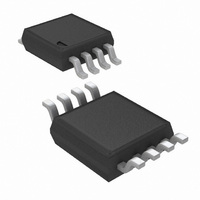
LM5068MM-3/NOPB National Semiconductor, LM5068MM-3/NOPB Datasheet - Page 11

LM5068MM-3/NOPB
Manufacturer Part Number
LM5068MM-3/NOPB
Description
IC CONTROLLER HOTSWAP -48V 8MSOP
Manufacturer
National Semiconductor
Type
Hot-Swap Controllerr
Datasheet
1.LM5068MM-3NOPB.pdf
(26 pages)
Specifications of LM5068MM-3/NOPB
Applications
General Purpose
Internal Switch(s)
No
Voltage - Supply
-10 V ~ -90 V
Operating Temperature
-40°C ~ 105°C
Mounting Type
Surface Mount
Package / Case
8-TSSOP, 8-MSOP (0.118", 3.00mm Width)
For Use With
LM5068EVAL - EVALUATION BOARD FOR LM5068
Lead Free Status / RoHS Status
Lead free / RoHS Compliant
Other names
LM5068MM-3
LM5068MM-3TR
LM5068MM-3TR
Available stocks
Company
Part Number
Manufacturer
Quantity
Price
Company:
Part Number:
LM5068MM-3/NOPB
Manufacturer:
National Semiconductor
Quantity:
1 821
Company:
Part Number:
LM5068MM-3/NOPB
Manufacturer:
NS
Quantity:
3 489
Function Description
The LM5068 is designed to facilitate the insertion and re-
moval of circuit cards into live backplanes in a controlled
manner. Because the supply bypass capacitors on the circuit
card can draw large transient currents, it is critical to control
the supply current during insertion to limit system power
glitches and connector damage. Controlling in-rush current
prevents other boards in the system from resetting during
board insertion. Load short-circuit protection is accom-
plished by active current limiting of the load current. The
topology of the LM5068 is illustrated in the simplified appli-
cation circuit shown in Figure 1.
Start-Up Operation
The LM5068 resides on a removable circuit card. Power is
applied to the load or power conversion circuitry through an
external N-Channel MOSFET switch and current sense re-
sistor.
When power is initially applied to the card, the gate of the
external MOSFET is held low. When certain interlock condi-
tions are met, a turn-on sequence begins and an internal 60
µA current source charges the gate of the MOSFET. To
initiate the start-up sequence, all of the following interlock
conditions must be satisfied:
When all of the interlock conditions are met, a 6 µA TIMER
current source is enabled to charge the timer capacitor C
During this initial timer sequence the GATE output is held
low. When the C
the TIMER circuit resets the timer capacitor to 1V and acti-
vates a 60 µA current source (I
• The input voltage V
• The voltage at UV is above 2.5V (V
• The voltage at OV falls below 2.5V (V
• The voltage on the Timer capacitor (C
• The GATE pin is below 0.5V (V
(V
TLVT
)
FIGURE 1. LM5068 Topology
T
capacitor successfully charges up to 4V,
DD
- V
EE
GATE
exceeds 9V(V
GLT
) into the MOSFET gate.
)
UV
OV
)
T
) is less than 1V
)
UVS
)
20078604
T
.
11
Over and Under-Voltage Lockout
The line Under-voltage lockout (UVLO) circuitry of the
LM5068 monitors V
V
V
less than 8.5V (V
mode. Raising the V
releases the V
In addition to the internal UVLO circuit, the UV and OV
comparators monitor the input line voltage through an exter-
nal resistor divider. Programmable UV and OV comparator
hysteresis is implemented with switched 20µA current
sources that raise or lower the OV and UV pins when the
comparators reach their threshold. Either UV or OV fault
conditions will switch the GATE pin low and disconnect the
power to the load. To restart the GATE pin, the supply
voltage must return to a level which is greater than the UV
fault and less than the OV fault threshold and all of the
interlock conditions (with the exception of the TIMER) must
be met.
Removal of the circuit card from the backplane initiates an
under-voltage condition. The series MOSFET is then dis-
abled to disconnect the source of power to the load. The
under-voltage threshold and hysteresis are programmed by
the external resistor divider connected to the UV pin.
Timer
The value of the C
LM5068’s timer delay and filter functions. There are four
charging and discharging modes:
1. 6µA slow charge for initial timing delay and post-fault
2. 240µA fast charge for circuit breaker delay.
3. 6µA slow discharge for circuit breaker "cool-off".
4. Low impedance switch to reset capacitor after initial
Current Control
The LM5068 has three current sense thresholds which pro-
tect the backplane supply and circuit card from overload
UVS
UVSH
re-try timer (LM5068-2 and -4)
timing delay, input under-voltage lockout, and during
over-voltage and under-voltage initial timing.
is the negative going threshold and the hysteresis is
(see Electrical Characteristics). A V
FIGURE 2. Hot Swap Controller
DD
UVLO and enables the controller.
UVS
DD
DD
T
) keeps the controller in a disabled
for under-voltage conditions, where
capacitor sets the duration of the
voltage above 9.1V (V
DD
20078605
UVS
- V
www.national.com
EE
+ V
voltage
UVSH
)


