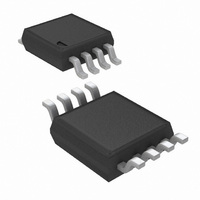
LM5068MM-3/NOPB National Semiconductor, LM5068MM-3/NOPB Datasheet - Page 2

LM5068MM-3/NOPB
Manufacturer Part Number
LM5068MM-3/NOPB
Description
IC CONTROLLER HOTSWAP -48V 8MSOP
Manufacturer
National Semiconductor
Type
Hot-Swap Controllerr
Datasheet
1.LM5068MM-3NOPB.pdf
(26 pages)
Specifications of LM5068MM-3/NOPB
Applications
General Purpose
Internal Switch(s)
No
Voltage - Supply
-10 V ~ -90 V
Operating Temperature
-40°C ~ 105°C
Mounting Type
Surface Mount
Package / Case
8-TSSOP, 8-MSOP (0.118", 3.00mm Width)
For Use With
LM5068EVAL - EVALUATION BOARD FOR LM5068
Lead Free Status / RoHS Status
Lead free / RoHS Compliant
Other names
LM5068MM-3
LM5068MM-3TR
LM5068MM-3TR
Available stocks
Company
Part Number
Manufacturer
Quantity
Price
Company:
Part Number:
LM5068MM-3/NOPB
Manufacturer:
National Semiconductor
Quantity:
1 821
Company:
Part Number:
LM5068MM-3/NOPB
Manufacturer:
NS
Quantity:
3 489
www.national.com
PIN
Connection Diagram
Pin Description
1
2
3
4
5
6
7
8
PWRGD
SENSE
TIMER
NAME
GATE
V
V
OV
UV
DD
EE
Open Drain Power Good indicator
Line Over-Voltage Shutdown
Line Under-Voltage Shutdown
Negative Supply Voltage Input
Current Sense Input
N-Channel MOSFET Gate Drive Output
Timer Input
Positive Supply Voltage Input
DESCRIPTION
2
Following a successful power-up sequence the PWRGD
signal will be active. The LM5068-1 and -2 are
configured for an active power-good state as HIGH,
while the LM5068-3 and –4 are configured for an active
power-good state as LOW.
An external resistor divider from the power source sets
the over-voltage shutdown level. Hysteresis is
generated by an internal current source which sources
20 µA into the external divider when the OV pin
exceeds 2.5V.
An external resistor divider from the power source sets
the under-voltage shutdown level. Hysteresis is set by
an internal current source which sinks 20 µA from the
external divider when the UV pin falls below 2.5V.
Load current is monitored via an external current sense
resistor (R
fault timer is initiated. Load current is actively limited to
100mV/R
a catastrophic fault, the fast gate pull down circuit will
reduce the MOSFET gate voltage and initiate active
current limiting.
This output is pulled high by a 60 µA current source to
turn on the MOSFET.
An external capacitor connected to this pin sets the
initial start-up delay and the delay to shutdown in the
event of an over-current condition. This pin is also used
for the automatic re-try timing sequence, following fault
shutdown (-2 and –4 versions).
s
. If the sense voltage exceeds 200mV due to
s
). If the voltage across R
20078602
APPLICATION INFORMATION
s
exceeds 50mV the


