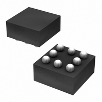
BD6067GU-E2 Rohm Semiconductor, BD6067GU-E2 Datasheet - Page 10

BD6067GU-E2
Manufacturer Part Number
BD6067GU-E2
Description
IC LED DRIVR WHITE BCKLGT 8-VCSP
Manufacturer
Rohm Semiconductor
Type
Backlight, White LEDr
Specifications of BD6067GU-E2
Topology
PWM, Step-Up (Boost)
Number Of Outputs
1
Internal Driver
Yes
Type - Primary
Backlight
Type - Secondary
White LED
Frequency
800kHz ~ 1.2MHz
Voltage - Supply
2.7 V ~ 5.5 V
Voltage - Output
30V
Mounting Type
Surface Mount
Package / Case
8-VCSP
Operating Temperature
-30°C ~ 85°C
Current - Output / Channel
30mA
Internal Switch(s)
Yes
Led Driver Application
Mobile Phones
No. Of Outputs
1
Output Current
30mA
Output Voltage
36V
Input Voltage
2.7V To 5.5V
Operating Temperature Range
-30°C To +85°C
Driver
RoHS Compliant
Lead Free Status / RoHS Status
Lead free / RoHS Compliant
Efficiency
-
Lead Free Status / Rohs Status
Details
Other names
BD6067GU-E2TR
Available stocks
Company
Part Number
Manufacturer
Quantity
Price
Company:
Part Number:
BD6067GU-E2
Manufacturer:
RICOH
Quantity:
3 000
Part Number:
BD6067GU-E2
Manufacturer:
ROHM/罗姆
Quantity:
20 000
© 2011 ROHM Co., Ltd. All rights reserved.
BD6067GU, BD6069GUT, BD6071HFN, BD6072HFN
►BD6071HFN
●Absolute maximum ratings (Ta=25℃)
●Recommended operating range (Ta=-30℃ ~+85℃)
●Electrical characteristic (Unless otherwise specified Ta = +25℃, Vin=3.6V)
●Electrical characteristic curves (Reference data)
www.rohm.com
5.0
4.0
3.0
2.0
1.0
0.0
Fig.21 Current Consumption vs.
Power supply voltage 1
Power supply voltage 2
Power dissipation
Operating temperature range
Storage temperature rang
*1 These values are based on GND and GNDA pins.
*2 When it’s used by more than Ta=25℃, it’s reduced by 5.04mW/℃.
Operating supply voltage
<EN Terminal>
EN threshold voltage (Low)
EN threshold voltage (High)
EN terminal input current
EN terminal output current
<Switching regulator>
Input voltage range
Quiescent Current
Current Consumption
Feedback voltage
Inductor current limit
SW saturation voltage
SW on resistance P
Switching frequency
Duty cycle limit
Output voltage range
Over voltage limit
Start up time
*1 This parameter is tested with dc measurement.
2.5
power source voltage
3
3.5
Parameter
Parameter
Parameter
Ta=25 ℃
Vin [V]
4
Ta=85 ℃
4.5
Ta=-30 ℃
5
5.5
Symbol
VMAX1
VMAX2
Symbol
Symbol
Ronp
VthH
Topr
VthL
Vsat
Duty
Tstg
fSW
Icoil
Iout
Vin
Vfb
Ovl
Vin
Idd
Pd
Vo
Iin
Ts
Iq
1.0
0.9
0.8
0.7
0.6
0.5
0.4
0.3
0.2
0.1
0.0
2.5
Fig.22 Quiescent current vs.
power source voltage
3
Min.
0.47
82.7
14.0
Min.
-2.0
200
2.7
1.4
3.1
0.8
-
-
-
-
-
-
-
-
3.5
-55 ~ +150
-30 ~ +85
10/29
Ratings
Ratings
Ta=-30, 25, 85 ℃
Vin [V]
630 *
Limits
20 *
Typ.
Typ.
18.3
0.50
0.14
85.0
14.5
-0.1
7 *
265
4
3.6
0.1
1.1
2.1
1.0
0.5
-
-
-
-
1
1
2
4.5
Max.
Max.
30.0
0.53
0.28
14.0
15.0
330
5.5
1.2
0.4
5.5
2.0
1.5
3.2
1.0
5
-
-
-
5.5
MHz
Unit
mW
Unit
Unit
mA
mA
ms
μA
μA
μA
℃
℃
%
Ω
V
V
V
V
V
V
V
V
V
V
Applicable to Vin,EN,VFB,
TEST pins
Applicable to SW,Vout pins
70mm×70mm×1.6mm at
glass epoxy board mounting
EN=5.5V
EN=0
EN=0V
EN=2.6V,VFB=1.0V,VIN=3.6V
Vin=3.6V
Isw=200mA, Vout=13V
Ipch=200mA,Vout=13V
VFB=0V
VFB=0V
1.4
1.3
1.2
1.1
0.9
0.8
0.7
0.6
1
Fig.23 Oscillation frequency vs.
2.5
power source voltage
3
*1
Conditions
Conditions
3.5
Conditions
Ta=-30 ℃
Vin [V]
4
2011.01 - Rev.C
Technical Note
4.5
Ta=25 ℃
Ta=85 ℃
5
5.5


