BD6067GU-E2 Rohm Semiconductor, BD6067GU-E2 Datasheet - Page 8
BD6067GU-E2
Manufacturer Part Number
BD6067GU-E2
Description
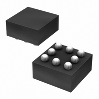
IC LED DRIVR WHITE BCKLGT 8-VCSP
Manufacturer
Rohm Semiconductor
Type
Backlight, White LEDr
Specifications of BD6067GU-E2
Topology
PWM, Step-Up (Boost)
Number Of Outputs
1
Internal Driver
Yes
Type - Primary
Backlight
Type - Secondary
White LED
Frequency
800kHz ~ 1.2MHz
Voltage - Supply
2.7 V ~ 5.5 V
Voltage - Output
30V
Mounting Type
Surface Mount
Package / Case
8-VCSP
Operating Temperature
-30°C ~ 85°C
Current - Output / Channel
30mA
Internal Switch(s)
Yes
Led Driver Application
Mobile Phones
No. Of Outputs
1
Output Current
30mA
Output Voltage
36V
Input Voltage
2.7V To 5.5V
Operating Temperature Range
-30°C To +85°C
Driver
RoHS Compliant
Lead Free Status / RoHS Status
Lead free / RoHS Compliant
Efficiency
-
Lead Free Status / Rohs Status
Details
Other names
BD6067GU-E2TR
Available stocks
Company
Part Number
Manufacturer
Quantity
Price
Company:

Part Number:
BD6067GU-E2
Manufacturer:
RICOH
Quantity:
3 000
Part Number:
BD6067GU-E2
Manufacturer:
ROHM/罗姆
Quantity:
20 000


© 2011 ROHM Co., Ltd. All rights reserved.
BD6067GU, BD6069GUT, BD6071HFN, BD6072HFN
►BD6067GU
●External components Selection Method
●Recommended PCB layout
www.rohm.com
<<Constants in the standard circuit example>>
R1: Determines the LED current I
L1: Coil for boost. The recommended value is 22µH. be sure to use a sufficient DC current permissible value and a sufficient
Cin: Power supplie bypass capacitor. This capacitor must be provided to remove an instantaneous power supply noise for
C0: Output smoothing capacitor. The capacitance recommended for BD6067GU is 1.0µF.
D1: Schottky barrier diode (SBD) for output rectification. To achieve high conversion efficiency, use a diode characterized by
When a PCB designed, the power supply line should be wired in a way that the board impedance can be minimized. If
necessary, the bypass capacitor must be connected. In particular, pins around the DC/DC converter must be wired in such a
way that the wiring impedance can be minimized. In addition, when a DC/DC converter using a coil is used, it is necessary to
place the output capacitor Cout, coil L1, rectification diode D1 and bypass capacitor CIN near this IC and keep the GND
impedance low.
<Recommended parts>
low DC resistance coil.
<Recommended parts>
stable voltage supply to this IC. To obtain good characteristics, the low ESR parts like the ceramics capacitor must be
used. The recommended capacitance is 1µF or more.
<Recommended parts>
<Recommended parts>
When selecting capacitors for Cin and C0, special care should be taken for rated voltage. The desirable rated voltage is
about double the voltage actually applied to the capacitor. When the margin for rated voltage is not sufficient, the
capacitance may be a half or less of the nominal value.
of low Vf, low reverse leak and high current capacity.
<Recommended parts>
Capacitance value
Capacitance value
Inductance value
I
LED
1.0µF
1.0µF
22µH
15
20
5
(mA)
To cell voltage source
Model number/manufacturer
RB160M-40 / ROHM
LED
GRM188B11A105KA61B / MURATA
UMK107C105KA-B / TAIYO YUDEN
NR3015T220M / TAIYO YUDEN
at power ON.
Model number/manufacturer
Model number/manufacturer
Model number/manufacturer
CIN
VOUT
GNDA
Fig.19 PCB Layout Image
VIN
R1[Ω]
39
13
10
D
COUT
1
SW
EN
8/29
L1
VDAC
VFB
To battery GND
GND
R
1
2011.01 - Rev.C
Technical Note
Related parts for BD6067GU-E2
Image
Part Number
Description
Manufacturer
Datasheet
Request
R

Part Number:
Description:
Multifunction LED Display Panel
Manufacturer:
CARLO GAVAZZI
Datasheet:

Part Number:
Description:
Manufacturer:
Rohm Semiconductor
Datasheet:
Part Number:
Description:
Manufacturer:
Rohm Semiconductor
Datasheet:
Part Number:
Description:
Manufacturer:
Rohm Semiconductor
Datasheet:
Part Number:
Description:
Manufacturer:
Rohm Semiconductor
Datasheet:
Part Number:
Description:
Manufacturer:
Rohm Semiconductor
Datasheet:
Part Number:
Description:
Manufacturer:
Rohm Semiconductor
Datasheet:
Part Number:
Description:
Manufacturer:
Rohm Semiconductor
Datasheet:
Part Number:
Description:
Manufacturer:
Rohm Semiconductor
Datasheet:
Part Number:
Description:
Manufacturer:
Rohm Semiconductor
Datasheet:
Part Number:
Description:
Manufacturer:
Rohm Semiconductor
Datasheet:
Part Number:
Description:
Manufacturer:
Rohm Semiconductor
Datasheet:
Part Number:
Description:
Manufacturer:
Rohm Semiconductor
Datasheet: