BD6067GU-E2 Rohm Semiconductor, BD6067GU-E2 Datasheet - Page 5
BD6067GU-E2
Manufacturer Part Number
BD6067GU-E2
Description
IC LED DRIVR WHITE BCKLGT 8-VCSP
Manufacturer
Rohm Semiconductor
Type
Backlight, White LEDr
Specifications of BD6067GU-E2
Topology
PWM, Step-Up (Boost)
Number Of Outputs
1
Internal Driver
Yes
Type - Primary
Backlight
Type - Secondary
White LED
Frequency
800kHz ~ 1.2MHz
Voltage - Supply
2.7 V ~ 5.5 V
Voltage - Output
30V
Mounting Type
Surface Mount
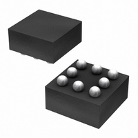
Package / Case
8-VCSP
Operating Temperature
-30°C ~ 85°C
Current - Output / Channel
30mA
Internal Switch(s)
Yes
Led Driver Application
Mobile Phones
No. Of Outputs
1
Output Current
30mA
Output Voltage
36V
Input Voltage
2.7V To 5.5V
Operating Temperature Range
-30°C To +85°C
Driver
RoHS Compliant
Lead Free Status / RoHS Status
Lead free / RoHS Compliant
Efficiency
-
Lead Free Status / Rohs Status
Details
Other names
BD6067GU-E2TR
Available stocks
Company
Part Number
Manufacturer
Quantity
Price
Company:

Part Number:
BD6067GU-E2
Manufacturer:
RICOH
Quantity:
3 000
Part Number:
BD6067GU-E2
Manufacturer:
ROHM/罗姆
Quantity:
20 000


© 2011 ROHM Co., Ltd. All rights reserved.
BD6067GU, BD6069GUT, BD6071HFN, BD6072HFN
►BD6067GU
●Release Circuit Protection
www.rohm.com
1) Operation
2) LED current control
3) Dimming control
BD6067GU is a constant frequency PWM current mode DC/DC converter. It is shown in the block diagram of Fig.11. In a
PWM comparator forming one of the PWM current mode features, one is an error element from the error amplifier and
another is an element produced by superimposing the inductor current on a slope waveform that prevents sub-harmonic
oscillation. This output controls Q1 via the RS latch. Energy is stored in an external inductor whileQ1 is ON and then it is
moved to the COUT capacitor via D1 while Q1 is OFF. In this way, voltage Vout higher than input voltage Vin can be
obtained. Because the above operation is performed in a way that the VFB pin voltage equals the Vfb voltage, the boost
voltage is dominantly determined by the expression “Vf × number of LEDs.”
The LED current is determined depending on the VFB pin voltage “Vfb” and the resistance connected to VFB.
I
▪ Control by PWM signal
LED
The startup condition of BD6067GU is controlled via the SHDNB/EN pin. It is powered OFF at 0.4V or less and powered
ON at 1.4V or more.
As shown in Fig.13, brightness is controlled in the BD6067GU via the PWM signal input the SHDNB/EN pin. In this way,
the LED current is controlled in a range from 0 to the maximum current. The average LED current increases in
proportion to the Duty cycle of the PWM signal. In the PWM off cycle, no current dissipation takes place in IC and LEDs,
resulting in high efficiency. Duties below 5% and above 95% must no be used for brightness control because they
significantly affects the leading and trailing edges. BD6067GU standard PWM frequency ranges from 100Hz to 300Hz.
is given below.
Vout voltage = (Vf × number of LEDs) + Vfb
I
LED
=200mV/ R1
Vin
Fig.13 Example of Brightness Control by PWM signal at the EN Pin
I
LED
10
12
15
20
[mA]
5
Vin
GNDA
22μH
L1
BD6067GU R1 [Ω]
SW
BD6067GU
GND
39
20
16
13
10
5/29
EN
VDAC
VFB
Vout
PWM
100Hz~300Hz
D1
1μF
10Ω
R1
I
LED
2011.01 - Rev.C
Technical Note
Related parts for BD6067GU-E2
Image
Part Number
Description
Manufacturer
Datasheet
Request
R

Part Number:
Description:
Multifunction LED Display Panel
Manufacturer:
CARLO GAVAZZI
Datasheet:

Part Number:
Description:
Manufacturer:
Rohm Semiconductor
Datasheet:
Part Number:
Description:
Manufacturer:
Rohm Semiconductor
Datasheet:
Part Number:
Description:
Manufacturer:
Rohm Semiconductor
Datasheet:
Part Number:
Description:
Manufacturer:
Rohm Semiconductor
Datasheet:
Part Number:
Description:
Manufacturer:
Rohm Semiconductor
Datasheet:
Part Number:
Description:
Manufacturer:
Rohm Semiconductor
Datasheet:
Part Number:
Description:
Manufacturer:
Rohm Semiconductor
Datasheet:
Part Number:
Description:
Manufacturer:
Rohm Semiconductor
Datasheet:
Part Number:
Description:
Manufacturer:
Rohm Semiconductor
Datasheet:
Part Number:
Description:
Manufacturer:
Rohm Semiconductor
Datasheet:
Part Number:
Description:
Manufacturer:
Rohm Semiconductor
Datasheet:
Part Number:
Description:
Manufacturer:
Rohm Semiconductor
Datasheet: