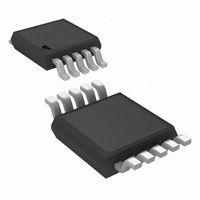
LM3445MM/NOPB National Semiconductor, LM3445MM/NOPB Datasheet - Page 14

LM3445MM/NOPB
Manufacturer Part Number
LM3445MM/NOPB
Description
IC LED DRIVER TRIAC DIMM 10-MSOP
Manufacturer
National Semiconductor
Series
PowerWise®r
Type
Triac Dimmabler
Specifications of LM3445MM/NOPB
Mfg Application Notes
LM3445 Reference Design
Constant Current
Yes
Topology
PWM, Step-Down (Buck)
Number Of Outputs
1
Internal Driver
No
Type - Secondary
High Brightness LED (HBLED)
Frequency
30kHz ~ 1MHz
Voltage - Supply
8 V ~ 12 V
Mounting Type
Surface Mount
Package / Case
10-MSOP, Micro10™, 10-uMAX, 10-uSOP
Operating Temperature
-40°C ~ 125°C
Current - Output / Channel
1A
Internal Switch(s)
Yes
Efficiency
85%
For Use With
LM3445-220VEVAL - BOARD EVAL LM3445 220VLM3445-120VSMEV - BOARD EVAL LM3445 110VLM3445TRIACEVAL - BOARD EVAL LM3445MM
Lead Free Status / RoHS Status
Lead free / RoHS Compliant
Voltage - Output
-
Other names
LM3445MMTR
Available stocks
Company
Part Number
Manufacturer
Quantity
Price
Company:
Part Number:
LM3445MM/NOPB
Manufacturer:
TI
Quantity:
7 000
www.national.com
MASTER/SLAVE OPERATION
Multiple LM3445s can be configured so that large strings of
LEDs can be controlled by a single triac dimmer. By doing so,
smooth consistent dimming for multiple LED circuits is
achieved.
When the FLTR1 pin is tied above 4.9V (typical), preferably
to VCC, the ramp comparator is tri-stated, disabling the dim
decoder. This allows one or more LM3445 devices or PWM
LED driver devices (slaves) to be controlled by a single
LM3445 (master) by connecting their DIM pins together.
MASTER/SLAVE CONFIGURATION
National Semiconductor offers an LM3445 demonstration
PCB for customer evaluation through our website. The fol-
lowing description and theory uses reference designators that
follow our evaluation PCB. The LM3445 Master/Slave
schematics are illustrated below (figures 13 - 15) for clarity.
Each board contains a separate circuit for the Master and
Slave function. Both the Master and Slave boards will need
to be modified from their original stand alone function so that
they can be coupled together. Only the Master LM3445 re-
quires use of the Master/Slave circuit for any number of
slaves.
14
MASTER BOARD MODIFICATIONS
•
•
•
SLAVE BOARD(S) MODIFICATIONS
•
•
MASTER/SLAVE(S) INTERCONNECTION
•
•
MASTER/SLAVE THEORY OF OPERATION
By placing two series diodes on the Master VCC circuit one
forces the master VCC UVLO to become the dominant thresh-
old. When Master VCC drops below UVLO, GATE stops
switching and the RC timer (>200 µs) rises above the TL431
threshold (2.5V) which in turn pulls down on the gate of the
Slave pass device (Q1).
The valley-fill circuit could consist of one large circuit to power
all LM3445 series connected, or each LM3445 circuit could
have a separate valley-fill circuit located near the buck con-
verter.
Remove R10 and replace with a BAS40 diode
Connect TP18 to TP14 (V
Connect TP17 (gate of Q5) to TP15 (gate of Q2)
Remove R11 (disconnects BLDR)
Tie TP14 (FLTR1) to V
Connect TP19 of Master to TP10 of Slave (Master VCC
Control)
Connect TP6 (DIM pin) of Master to TP6 (DIM pin) of Slave
(Master DIM Control)
CC
CC
)


