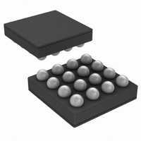
LM3554TME/NOPB National Semiconductor, LM3554TME/NOPB Datasheet - Page 33

LM3554TME/NOPB
Manufacturer Part Number
LM3554TME/NOPB
Description
IC LED DVR PHOTO FLASH 16-USMD
Manufacturer
National Semiconductor
Type
Photo Flash LED (I²C Interface)r
Datasheet
1.LM3554TMENOPB.pdf
(40 pages)
Specifications of LM3554TME/NOPB
Constant Current
Yes
Topology
High Side, Step-Up (Boost)
Number Of Outputs
2
Internal Driver
Yes
Type - Primary
Flash/Torch
Type - Secondary
White LED
Frequency
2MHz
Voltage - Supply
2.7 V ~ 5.5 V
Voltage - Output
5V
Mounting Type
Surface Mount
Package / Case
16-MicroSMD
Operating Temperature
-30°C ~ 85°C
Current - Output / Channel
600mA
Internal Switch(s)
Yes
Efficiency
90%
Led Driver Application
LED Backlighting, Portable Electronics
No. Of Outputs
2
Output Current
1.2A
Input Voltage
2.7V To 5.5V
Dimming Control Type
I2C
Rohs Compliant
Yes
Lead Free Status / RoHS Status
Lead free / RoHS Compliant
Other names
LM3554TMETR
CONFIGURATION REGISTER 2
Configuration Register 2 contains the bits to select if TX2,
NTC, and the VIN monitor force Torch mode or force the Flash
GPIO REGISTER
The GPIO register contains the control bits which change the
state of the TX1/TORCH/GPIO1 pin and the ENVM/TX2/
GPIO2 pin to general purpose I/O’s (GPIO’s). Additionally, bit
[6] of this register configures the ENVM/TX2/GPIO2 as a
Reads Back '1' Reads Back '1' Reads Back '1' Reads Back '1' 0 = If IN drops
Bit 7 (Not
used)
Bit 6 (Not
used)
Bit 5 (Not
used)
FIGURE 21. Configuration Register 2 Description
TABLE 7. Configuration Register 2 Bit Settings
FIGURE 22. GPIO Register Description
Bit 4 (Not
used)
33
1 = If IN drops
threshold and
threshold and
LED's turn off
programmed
programmed
enabled, the
enabled, the
Torch mode
Shutdown)
forced into
LED's are
below the
below the
Bit 3 (V
feature is
feature is
(default)
LEDs into shutdown. Additionally, bit [2] (AET bit) selects the
Alternate External Torch mode (see
Monitor
hardware interrupt output reflecting the NTC flag bit in the
Flags Register.
scription and functionality of the GPIO register.
the VIN
Monitor
the VIN
Monitor
IN
STROBE (TX1
1 = Alternative
External Torch
mode with no
timeout (TX1
operation for
TX1/TORCH
TX1/TORCH
forces Torch
0 = Normal
high before
mode only)
high before
mode only)
Bit 2 (AET
operation.
STROBE
Figure 22
default
mode)
and
0 = LEDI/NTC
1 = LEDI/NTC
only) default
Torch mode
Shutdown)
below V
(NTC mode
below V
(NTC mode
forces the
LEDs into
forces the
LEDs into
shutdown
pin going
pin going
Table 8
(NTC
Bit 1
only)
Figure 21
30042026
30042036
TRIP
TRIP
describe the bit de-
0 = TX2 event
1 = TX2 event
only) default
Torch mode
Shutdown)
and
(TX2 mode
(TX2 mode
forces the
LEDs into
forces the
LEDs into
shutdown
www.national.com
Bit 0
(TX2
only)
Table
7).


