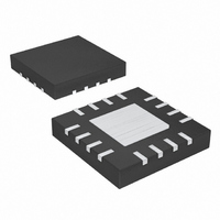
MAX16823ATE+ Maxim Integrated Products, MAX16823ATE+ Datasheet - Page 6

MAX16823ATE+
Manufacturer Part Number
MAX16823ATE+
Description
IC LED DRIVR HIGH BRIGHT 16-TQFN
Manufacturer
Maxim Integrated Products
Type
HBLED Driverr
Datasheet
1.MAX16823ATE.pdf
(12 pages)
Specifications of MAX16823ATE+
Constant Current
Yes
Topology
Linear (LDO), Open Drain, PWM
Number Of Outputs
3
Internal Driver
Yes
Type - Primary
Automotive
Type - Secondary
High Brightness LED (HBLED), RGB
Voltage - Supply
5.5 V ~ 40 V
Voltage - Output
3.41V
Mounting Type
Surface Mount
Package / Case
16-TQFN Exposed Pad
Operating Temperature
-40°C ~ 125°C
Current - Output / Channel
100mA
Internal Switch(s)
Yes
Operating Supply Voltage
5.5 V to 40 V
Maximum Power Dissipation
2666 mW
Maximum Operating Temperature
+ 125 C
Mounting Style
SMD/SMT
Minimum Operating Temperature
- 40 C
Lead Free Status / RoHS Status
Lead free / RoHS Compliant
Frequency
-
Efficiency
-
Lead Free Status / Rohs Status
Lead free / RoHS Compliant
High-Voltage, 3-Channel Linear High-Brightness
LED Driver with Open LED Detection
The MAX16823 three-channel current regulator operates
from a 5.5V to 40V input voltage range and delivers up
to 100mA per channel to one or more strings of
HBLEDs. The output currents are programmable using
external current-sense resistors in series with the LEDs.
Three DIM inputs allow a wide range of independent
pulsed dimming in addition to providing the on and off
control of the outputs. The MAX16823 offers an LED-
GOOD output that indicates an open-circuit condition
when one or more LED channels are open.
Integrated pass elements minimize external compo-
nents while providing ±5% output current accuracy.
Additional features include a 3.4V (±5%) voltage regula-
tor with 4mA output current capability, short-circuit and
thermal protection.
The MAX16823 uses a feedback loop to linearly control
the current from each output. The voltage across each
sense resistor is compared to a fixed reference voltage
and the error is amplified to drive the internal power
pass device for a particular channel. See the Block
Diagram . The regulation point is factory-set at 203mV.
The regulated current is adjusted by the value of
R
The MAX16823 is a constant-current LED driver inter-
nally optimized for driving the impedance range
expected from one or more HBLEDs.
The MAX16823 includes a fixed 3.4V voltage regulator
that delivers up to 4mA of load current for auxiliary
applications throughout the 5.5V to 40V input voltage
range. Connect a 0.1µF compensation capacitor from
REG to ground. Shorting REG to ground disables the
thermal shutdown.
The MAX16823 enters a thermal-shutdown mode in the
event of overheating. This typically occurs in overload or
output short-circuit conditions. When the junction temper-
ature exceeds T
tion circuitry turns off the series pass elements. The
MAX16823 recovers from thermal-shutdown mode once
the junction temperature drops by 23°C. The part will
therefore protect itself by low-frequency thermal cycling
in the event of a short-circuit or overload condition.
6
CS__
_______________________________________________________________________________________
.
J
= +155°C, the internal thermal protec-
Detailed Description
3.4V Regulator (REG)
Thermal Protection
The MAX16823 uses sense resistors to set the output
current for each channel. To set the LED current for a
particular channel, connect a sense resistor across the
corresponding current-sense input (CS_) and GND. For
optimal accuracy, connect the low-side of the current-
sense resistors to the IC’s ground pin with short traces.
The value needed for the sense resistor for a given cur-
rent can be calculated with the equation below:
where V
current (I
For proper operation, the minimum input voltage must
always be:
where V
connected LEDs. The minimum operating voltage of
the device is 5.5V.
The MAX16823 features an active-low, open-drain
LEDGOOD output that goes low either when one or
more LED channels are open or when a signal at any of
the dimming inputs remains low for a period greater
than the programmed LEDGOOD delay time t
Program t
LGC and ground. The LEDGOOD output goes low after
the programmed delay period t
the following formula to set the delay period:
where C
and ground. The LEDGOOD output goes low during
the thermal shutdown.
V
IN MIN
FT(MAX)
LGC
CS_
LED
(
DELAY
).
t
)
is 203mV and I
DELAY
is the capacitor connected between LGC
≥
Applications Information
V
is the total forward voltage of all series-
Programming the LED Current
R
CS MAX
with a capacitor connected between
Input-Voltage Considerations
CS
_(
=
_
257 900
( )
Ω =
,
)
+
I
V
OUT
V
CS
OUT_
( )
FT MAX
Ω
DELAY
(
_
_
×
( )
( )
V
A
C
is the desired LED
LGC
)
+
has elapsed. Use
V
( )
DO MAX
F
LEDGOOD
(
)
DELAY
.


