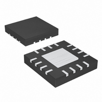
MAX16823ATE+ Maxim Integrated Products, MAX16823ATE+ Datasheet - Page 8

MAX16823ATE+
Manufacturer Part Number
MAX16823ATE+
Description
IC LED DRIVR HIGH BRIGHT 16-TQFN
Manufacturer
Maxim Integrated Products
Type
HBLED Driverr
Datasheet
1.MAX16823ATE.pdf
(12 pages)
Specifications of MAX16823ATE+
Constant Current
Yes
Topology
Linear (LDO), Open Drain, PWM
Number Of Outputs
3
Internal Driver
Yes
Type - Primary
Automotive
Type - Secondary
High Brightness LED (HBLED), RGB
Voltage - Supply
5.5 V ~ 40 V
Voltage - Output
3.41V
Mounting Type
Surface Mount
Package / Case
16-TQFN Exposed Pad
Operating Temperature
-40°C ~ 125°C
Current - Output / Channel
100mA
Internal Switch(s)
Yes
Operating Supply Voltage
5.5 V to 40 V
Maximum Power Dissipation
2666 mW
Maximum Operating Temperature
+ 125 C
Mounting Style
SMD/SMT
Minimum Operating Temperature
- 40 C
Lead Free Status / RoHS Status
Lead free / RoHS Compliant
Frequency
-
Efficiency
-
Lead Free Status / Rohs Status
Lead free / RoHS Compliant
High-Voltage, 3-Channel Linear High-Brightness
LED Driver with Open LED Detection
ICM7555. When V
V
the LEDs light up to full brightness. See the ICM7555
data sheet for formulas to calculate the dimming fre-
quency and the duty cycle.
Figure 3 shows a circuit with DIM1, DIM2, DIM3, and
LEDGOOD connected through a resistor to V
circuit is useful for applications that require all outputs
to latch off when one of the LEDs opens. The
MAX16823 resumes current regulation again through
power cycling, once the fault condition is removed.
Figure 1. LEDGOOD Timing Delay
Figure 2. PWM Dimming Operation with ICM7555
8
STOP
_______________________________________________________________________________________
. The PWM dimming operation is disabled and
C2
R3
TH
R2
DIS
TRG
STOP
ICM7555
STOP
TAIL
GND
IN
OUT
is present, DIM is pulled up to
LEDGOOD
R1
DIM
100kΩ
D3
Outputs Latch-Off
D2
D1
D4
C1
t
REG
ON
IN
DIM1
DIM2
DIM3
. This
MAX16823
GND
t
The application circuit in Figure 4 implements a two-
level brightness current for TAIL/STOP lights. In TAIL
operation, Q1 is off and R
STOP operation, Q1 turns on and the output current is
set by a parallel combination of R
Figure 5 shows an application circuit with the
MAX16823 using a single BJT to provide high output
current. For proper operation:
For minimized dropout, the LEDs can be placed in the
collector.
OFF
V
IN MIN
(
OUT3
OUT2
OUT1
REG
CS1
CS2
CS3
)
>
0.1μF
V
LEDGOOD GOES
LOW WHEN t
BE MAX
(
R
CS1
OFF
)
+
> t
V
DELAY
CS1
FT MAX
LEDs
(
R
CS2
sets the output current. In
Other Applications
)
CS1
+
V
CS
and R2.
R
CS3
_
+
V
DO MAX
(
)


