LP5521TMX/NOPB National Semiconductor, LP5521TMX/NOPB Datasheet - Page 13
LP5521TMX/NOPB
Manufacturer Part Number
LP5521TMX/NOPB
Description
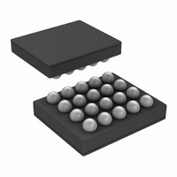
IC LED DRIVER RGB 25-USMD
Manufacturer
National Semiconductor
Series
PowerWise®r
Type
RGB LED Driverr
Datasheet
1.LP5521TMNOPB.pdf
(40 pages)
Specifications of LP5521TMX/NOPB
Constant Current
Yes
Topology
PWM, Switched Capacitor (Charge Pump)
Number Of Outputs
3
Internal Driver
Yes
Type - Primary
Backlight, Light Management Unit (LMU)
Type - Secondary
RGB
Frequency
1.25MHz
Voltage - Supply
2.7 V ~ 5.5 V
Voltage - Output
4.55V
Mounting Type
Surface Mount
Package / Case
20-MicroSMD
Operating Temperature
-30°C ~ 85°C
Current - Output / Channel
25.5mA
Internal Switch(s)
Yes
Efficiency
95%
Lead Free Status / RoHS Status
Lead free / RoHS Compliant
Other names
LP5521TMX
Available stocks
Company
Part Number
Manufacturer
Quantity
Price
Company:

Part Number:
LP5521TMX/NOPB
Manufacturer:
TI
Quantity:
57 001
Part Number:
LP5521TMX/NOPB
Manufacturer:
TI/德州仪器
Quantity:
20 000


Modes of Operation
RESET:
STANDBY:
STARTUP:
NORMAL:
POWER SAVE: In POWER SAVE mode analog blocks are disabled to minimize power consumption. See chapter Power Save
In the RESET mode all the internal registers are reset to the default values. Reset is done always if Reset Register
(0DH) is written FFH or internal Power On Reset is activated. Power On Reset (POR) will activate when supply
voltage is connected or when the supply voltage V
inactivate and the chip will continue to the STANDBY mode. CHIP_EN control bit is low after POR by default.
The STANDBY mode is entered if the register bit CHIP_EN or EN pin is LOW and Reset is not active. This is the
low power consumption mode, when all circuit functions are disabled. Registers can be written in this mode if
EN pin is high. Control bits are effective after start up.
When CHIP_EN bit is written high and EN pin is high, the INTERNAL STARTUP SEQUENCE powers up all the
needed internal blocks (V
the Thermal Shutdown (TSD) disables the chip operation and the chip state is in STARTUP mode, until no thermal
shutdown event is present.(Note 3)
During NORMAL mode the user controls the chip using the Control Registers. If EN pin is set low, the CHIP_EN
bit is reset to 0.
Mode for further information.
REF
, Bias, Oscillator etc.). Startup delay is 500 μs. If the chip temperature rises too high,
13
DD
falls below 1.5V. Once V
20186275
DD
rises above 1.5V, POR will
www.national.com
Related parts for LP5521TMX/NOPB
Image
Part Number
Description
Manufacturer
Datasheet
Request
R

Part Number:
Description:
Manufacturer:
National Semiconductor
Datasheet:

Part Number:
Description:
IC LED DRIVER RGB 25-USMD
Manufacturer:
National Semiconductor
Datasheet:

Part Number:
Description:
Programmable Three Channel LED Driver
Manufacturer:
NSC [National Semiconductor]
Datasheet:
Part Number:
Description:
National Semiconductor [8-Bit D/A Converter]
Manufacturer:
National Semiconductor
Datasheet:
Part Number:
Description:
National Semiconductor [Media Coprocessor]
Manufacturer:
National Semiconductor
Datasheet:
Part Number:
Description:
Digitally Controlled Tone and Volume Circuit with Stereo Audio Power Amplifier, Microphone Preamp Stage and National 3D Sound
Manufacturer:
National Semiconductor
Datasheet:
Part Number:
Description:
Digitally Controlled Tone and Volume Circuit with Stereo Audio Power Amplifier, Microphone Preamp Stage and National 3D Sound
Manufacturer:
National Semiconductor
Datasheet:
Part Number:
Description:
AC97 Rev 2 Codec with Sample Rate Conversion and National 3D Sound
Manufacturer:
National Semiconductor
Part Number:
Description:
Manufacturer:
National Semiconductor
Datasheet:
Part Number:
Description:
Manufacturer:
National Semiconductor
Datasheet:
Part Number:
Description:
General Purpose, Low Voltage, Low Power, Rail-to-Rail Output Operational Amplifiers
Manufacturer:
National Semiconductor
Datasheet:
Part Number:
Description:
8-bit 20 MSPS flash A/D converter.
Manufacturer:
National Semiconductor
Datasheet:
Part Number:
Description:
Low Noise Quad Operational Amplifier
Manufacturer:
National Semiconductor
Datasheet:
Part Number:
Description:
Quad Differential Line Receivers
Manufacturer:
National Semiconductor
Datasheet: