LP5521TMX/NOPB National Semiconductor, LP5521TMX/NOPB Datasheet - Page 23
LP5521TMX/NOPB
Manufacturer Part Number
LP5521TMX/NOPB
Description
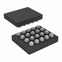
IC LED DRIVER RGB 25-USMD
Manufacturer
National Semiconductor
Series
PowerWise®r
Type
RGB LED Driverr
Datasheet
1.LP5521TMNOPB.pdf
(40 pages)
Specifications of LP5521TMX/NOPB
Constant Current
Yes
Topology
PWM, Switched Capacitor (Charge Pump)
Number Of Outputs
3
Internal Driver
Yes
Type - Primary
Backlight, Light Management Unit (LMU)
Type - Secondary
RGB
Frequency
1.25MHz
Voltage - Supply
2.7 V ~ 5.5 V
Voltage - Output
4.55V
Mounting Type
Surface Mount
Package / Case
20-MicroSMD
Operating Temperature
-30°C ~ 85°C
Current - Output / Channel
25.5mA
Internal Switch(s)
Yes
Efficiency
95%
Lead Free Status / RoHS Status
Lead free / RoHS Compliant
Other names
LP5521TMX
Available stocks
Company
Part Number
Manufacturer
Quantity
Price
Company:

Part Number:
LP5521TMX/NOPB
Manufacturer:
TI
Quantity:
57 001
Part Number:
LP5521TMX/NOPB
Manufacturer:
TI/德州仪器
Quantity:
20 000


Logic Interface Operational Description
LP5521 features a flexible logic interface for connecting to
processor and peripheral devices. Communication is done
with I
pins makes it possible to synchronize operation of several
devices.
IO Levels
I
fined by EN pin. Using EN pin as voltage reference for logic
inputs simplifies PWB routing and eliminates the need for
dedicated V
EN pin connections.
ADDR_SEL0/1 are referenced to V
is defined by V
GPO/INT pins
LP5521 has one General Purpose Output pin (GPO) and also
INT pin can be configured as a GPO pin. When INT is con-
figured as GPO output, it's level is defined by the V
State of the pins can be controlled with GPO register (0EH).
GPO pins are digital CMOS outputs and no pull-up/down re-
sistors are needed.
When INT pin GPO function is disabled, it operates as an
open drain pin. INT signal is active low, i.e. when interrupt
signal is sent, the pin is pulled to GND. External pull-up re-
sistor is needed for proper functionality.
2
C interface, CLK_32K and TRIG pins input levels are de-
2
C compatible interface and different logic input/output
Using EN pin as digital IO voltage reference
IO
pin. In the following block diagram is described
DD
voltage.
DD
voltage. GPO pin level
20186254
DD
voltage.
23
TRIG pin
TRIG pin can function as an external trigger input or output.
External trigger signal is active low, i.e. when trigger is sent/
received the pin is pulled to GND. TRIG is an open drain pin
and external pull-up resistor is needed for trigger line. Exter-
nal trigger input signal must be at least two 32 kHz clock
cycles long to be recognized. Trigger output signal is three 32
kHz clock cycles long. If TRIG pin is not used on application,
it should be connected to GND to prevent floating of this pin
and extra current consumption.
ADDR_SEL0,1 pins
ADDR_SEL0,1 pins define the chip I
erenced to V
Interface chapter for I
CLK_32K pin
CLK_32K pin is used for connecting external 32 kHz clock to
LP5521. External clock can be used to synchronize the se-
quence engines of several LP5521. Using external clock can
also improve automatic power save mode efficiency, because
internal clock can be switched off automatically when device
has entered power save mode, and external clock is present.
See application note “LP5521 Power Efficiency Consider-
ations” for more information.
Device can be used without the external clock. If external
clock is not used on the application, CLK_32K pin should be
connected to GND to prevent floating of this pin and extra
current consumption.
INT_AS_GPO
Name
GPO
INT
DD
signal level. See I
Bit Description
2
1
0
GPO register (0EH)
2
C address definitions.
Enable INT pin GPO function
0 = INT pin functions as a INT pin
1 = INT pin functions as a GPO pin
0 = GPO pin state is low
1 = GPO pin state is high
0 = INT pin state is low
(INT_AS_GPO=1)
1 = INT pin state is high
(INT_AS_GPO=1)
2
C Compatible Serial Bus
2
C address. Pins are ref-
www.national.com
Related parts for LP5521TMX/NOPB
Image
Part Number
Description
Manufacturer
Datasheet
Request
R

Part Number:
Description:
Manufacturer:
National Semiconductor
Datasheet:

Part Number:
Description:
IC LED DRIVER RGB 25-USMD
Manufacturer:
National Semiconductor
Datasheet:

Part Number:
Description:
Programmable Three Channel LED Driver
Manufacturer:
NSC [National Semiconductor]
Datasheet:
Part Number:
Description:
National Semiconductor [8-Bit D/A Converter]
Manufacturer:
National Semiconductor
Datasheet:
Part Number:
Description:
National Semiconductor [Media Coprocessor]
Manufacturer:
National Semiconductor
Datasheet:
Part Number:
Description:
Digitally Controlled Tone and Volume Circuit with Stereo Audio Power Amplifier, Microphone Preamp Stage and National 3D Sound
Manufacturer:
National Semiconductor
Datasheet:
Part Number:
Description:
Digitally Controlled Tone and Volume Circuit with Stereo Audio Power Amplifier, Microphone Preamp Stage and National 3D Sound
Manufacturer:
National Semiconductor
Datasheet:
Part Number:
Description:
AC97 Rev 2 Codec with Sample Rate Conversion and National 3D Sound
Manufacturer:
National Semiconductor
Part Number:
Description:
Manufacturer:
National Semiconductor
Datasheet:
Part Number:
Description:
Manufacturer:
National Semiconductor
Datasheet:
Part Number:
Description:
General Purpose, Low Voltage, Low Power, Rail-to-Rail Output Operational Amplifiers
Manufacturer:
National Semiconductor
Datasheet:
Part Number:
Description:
8-bit 20 MSPS flash A/D converter.
Manufacturer:
National Semiconductor
Datasheet:
Part Number:
Description:
Low Noise Quad Operational Amplifier
Manufacturer:
National Semiconductor
Datasheet:
Part Number:
Description:
Quad Differential Line Receivers
Manufacturer:
National Semiconductor
Datasheet: