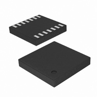
SI8235BB-C-IMR Silicon Laboratories Inc, SI8235BB-C-IMR Datasheet - Page 24

SI8235BB-C-IMR
Manufacturer Part Number
SI8235BB-C-IMR
Description
IC ISODRIVER DUAL LOW SIDE 14LGA
Manufacturer
Silicon Laboratories Inc
Datasheet
1.SI8234BB-C-IS1.pdf
(52 pages)
Specifications of SI8235BB-C-IMR
Configuration
Low-Side
Input Type
Non-Inverting
Delay Time
60ns
Current - Peak
4A
Number Of Configurations
2
Number Of Outputs
2
Voltage - Supply
6.5 V ~ 24 V
Operating Temperature
-40°C ~ 125°C
Mounting Type
Surface Mount
Package / Case
14-LGA
Lead Free Status / RoHS Status
Lead free / RoHS Compliant
High Side Voltage - Max (bootstrap)
-
Si823x
3.6. Layout Considerations
It is most important to minimize ringing in the drive path and noise on the Si823x VDD lines. Care must be taken to
minimize parasitic inductance in these paths by locating the Si823x as close to the device it is driving as possible.
In addition, the VDD supply and ground trace paths must be kept short. For this reason, the use of power and
ground planes is highly recommended. A split ground plane system having separate ground and VDD planes for
power devices and small signal components provides the best overall noise performance.
3.7. Undervoltage Lockout Operation
Device behavior during start-up, normal operation and shutdown is shown in Figure 35, where UVLO+ and UVLO-
are the positive-going and negative-going thresholds respectively. Note that outputs VOA and VOB default low
when input side power supply (VDDI) is not present.
3.7.1. Device Startup
Outputs VOA and VOB are held low during power-up until VDD is above the UVLO threshold for time period
tSTART. Following this, the outputs follow the states of inputs VIA and VIB.
3.7.2. Undervoltage Lockout
Undervoltage Lockout (UVLO) is provided to prevent erroneous operation during device startup and shutdown or
when VDD is below its specified operating circuits range. The input (control) side, Driver A and Driver B, each have
their own undervoltage lockout monitors.
The Si823x input side enters UVLO when VDDI < VDDI
outputs, VOA and VOB, remain low when the input side of the Si823x is in UVLO and their respective VDD supply
(VDDA, VDDB) is within tolerance. Each driver output can enter or exit UVLO independently. For example, VOA
unconditionally enters UVLO when VDDA falls below VDDA
VDDA
24
DISABLE
UVLO+
VDDI
UVLO-
UVLO+
VDDA
VIA
UVLO-
VOA
UV+
tSTART
.
VDD
VDD
Figure 35. Device Behavior during Normal Operation and Shutdown
HYS
HYS
tSD
tSTART
tSTART
Rev. 1.1
UV–
tSD
, and exits UVLO when VDDI > VDDI
UV–
tRESTART
and exits UVLO when VDDA rises above
tPHL
tPLH
UV+
. The driver


