TC4467MJD Microchip Technology, TC4467MJD Datasheet - Page 9
TC4467MJD
Manufacturer Part Number
TC4467MJD
Description
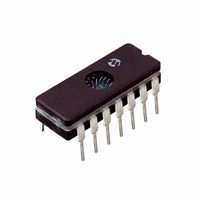
IC MOSFET DVR QUAD NAND 14CDIP
Manufacturer
Microchip Technology
Type
Microcontrollerr
Datasheet
1.TC4469CPD.pdf
(22 pages)
Specifications of TC4467MJD
Configuration
Low-Side
Input Type
NAND
Delay Time
40ns
Current - Peak
1.2A
Number Of Configurations
4
Number Of Outputs
4
Voltage - Supply
4.5 V ~ 18 V
Operating Temperature
-55°C ~ 125°C
Mounting Type
Through Hole
Package / Case
14-CDIP (0.300", 7.62mm)
Rise Time
25 ns
Fall Time
25 ns
Supply Voltage (min)
4.5 V
Supply Current
4 mA
Maximum Power Dissipation
840 mW
Maximum Operating Temperature
+ 125 C
Mounting Style
Through Hole
Minimum Operating Temperature
- 55 C
Number Of Drivers
4
Lead Free Status / RoHS Status
Lead free / RoHS Compliant
High Side Voltage - Max (bootstrap)
-
Lead Free Status / Rohs Status
Lead free / RoHS Compliant
Available stocks
Company
Part Number
Manufacturer
Quantity
Price
Company:

Part Number:
TC4467MJD
Manufacturer:
VISHAY
Quantity:
6 000


4.0
4.1
Large currents are required to charge and discharge
large capacitive loads quickly. For example, charging a
1000 pF load to 18 V in 25 nsec requires 0.72 A from
the device's power supply.
To ensure low supply impedance over a wide frequency
range, a 1 µF film capacitor in parallel with one or two
low-inductance, 0.1 µF ceramic disk capacitors with
short lead lengths (<0.5 in.) normally provide adequate
bypassing.
4.2
The TC4467 and TC4469 contain inverting drivers.
Potential
impedances from input to output will appear as
negative feedback and degrade switching speed
characteristics. Instead, individual ground returns for
input and output circuits, or a ground plane, should be
used.
4.3
The input voltage level changes the no-load or
quiescent supply current. The N-channel MOSFET
input stage transistor drives a 2.5 mA current source
load. With logic “0” outputs, maximum quiescent supply
current is 4 mA. Logic “1” output level signals reduce
quiescent current to 1.4 mA, maximum. Unused driver
inputs must be connected to V
power dissipation occurs for logic “1” outputs.
The drivers are designed with 50 mV of hysteresis,
which provides clean transitions and minimizes output
stage current spiking when changing states. Input volt-
age thresholds are approximately 1.5 V, making any
voltage greater than 1.5 V, up to V
Input current is less than 1 µA over this range.
2002 Microchip Technology Inc.
Supply Bypassing
Grounding
Input Stage
DETAILED DESCRIPTION
drops
developed
in
DD
DD
common
or V
, a logic “1” input.
SS
. Minimum
ground
TC4467/TC4468/TC4469
4.4
The supply current versus frequency and supply
current versus capacitive load characteristic curves will
aid in determining power dissipation calculations.
Microchip Technology's CMOS drivers have greatly
reduced quiescent DC power consumption.
Input signal duty cycle, power supply voltage and load
type influence package power dissipation. Given power
dissipation and package thermal resistance, the maxi-
mum
calculated. The 14-pin plastic package junction-to-
ambient thermal resistance is 83.3°C/W. At +70°C, the
package is rated at 800 mW maximum dissipation.
Maximum allowable chip temperature is +150°C.
Three components make up total package power
dissipation:
1.
2.
3.
A capacitive-load-caused dissipation (driving MOSFET
gates), is a direct function of frequency, capacitive load
and supply voltage. The power dissipation is:
EQUATION
A
referenced loads is a function of duty cycle, load
current and load voltage. The power dissipation is:
EQUATION
resistive-load-caused
Load-caused dissipation (P
Quiescent power (P
Transition power (P
f
C
V
D
V
V
I
L
S
=
S
L
ambient
=
=
=
=
Power Dissipation
=
=
Switching Frequency
Capacitive Load
Duty Cycle
Supply Voltage
Load Current
Supply Voltage
Load Voltage
P
L
operating
=
P
L
D V
=
T
Q
).
).
fCV
S
–
dissipation
V
temperature
2
S
L
L
).
I
L
DS21425B-page 9
for
is
ground-
easily
Related parts for TC4467MJD
Image
Part Number
Description
Manufacturer
Datasheet
Request
R

Part Number:
Description:
Manufacturer:
Microchip Technology Inc.
Datasheet:
Part Number:
Description:
Manufacturer:
Microchip Technology Inc.
Datasheet:
Part Number:
Description:
Manufacturer:
Microchip Technology Inc.
Datasheet:
Part Number:
Description:
Manufacturer:
Microchip Technology Inc.
Datasheet:
Part Number:
Description:
Manufacturer:
Microchip Technology Inc.
Datasheet:
Part Number:
Description:
Manufacturer:
Microchip Technology Inc.
Datasheet:
Part Number:
Description:
Manufacturer:
Microchip Technology Inc.
Datasheet:
Part Number:
Description:
Manufacturer:
Microchip Technology Inc.
Datasheet: