MC33931VW Freescale Semiconductor, MC33931VW Datasheet
MC33931VW
Specifications of MC33931VW
Available stocks


Related parts for MC33931VW

MC33931VW Summary of contents
Page 1
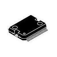
... Freescale Semiconductor, Inc., 2008. All rights reserved. Document Number: MC33931 33931 THROTTLE CONTROL H-BRIDGE VW SUFFIX (PB-FREE) 98ARH98330A 44-PIN HSOP WITH PROTRUDING HEAT SINK ORDERING INFORMATION Temperature Device Range (T MC33931VW/R2 -40°C to 125°C V PWR 33931 SF VPWR FB CCP OUT1 IN1 MOTOR IN2 ...
Page 2
... Figure 2. 33931 Simplified Internal Block Diagram 33931 2 INTERNAL BLOCK DIAGRAM VDD HS1 TO GATES HS1 LS1 LS1 HS2 LS2 VSENSE ILIM PWM CONSTANT OFF-TIME PWM CURRENT REGULATOR VPWR HS2 OUT1 OUT2 LS2 LS2 PGND CURRENT MIRROR AND PGND Analog Integrated Circuit Device Data Freescale Semiconductor ...
Page 3
... Logic Input Disable Input Analog Output 3 EN/D2 Logic Input 4-6,40,39 VPWR Power Input 7-9 OUT1 Power H-bridge Output 1 Output 10,11,34,35 PGND Power Ground 36-38 OUT2 Power H-bridge Output 2 Output Analog Integrated Circuit Device Data Freescale Semiconductor PIN CONNECTIONS AGND Tab Tab Figure 3 ...
Page 4
... The low-current analog signal ground must be connected to PGND via low- Analog Signal impedance path (<10 mΩ kHz). Exposed TAB is also the main Ground heatsinking path for the device. Pin is not used No Connect page 11. Definition < 0.4 V CEsat Analog Integrated Circuit Device Data Freescale Semiconductor ...
Page 5
... Maximum current at maximum die temperature represents ~ conduction loss heating in the diagonal pair of output MOSFETs. Therefore, the R < 5.0°C/W for maximum current at 70°C ambient. Module thermal design must be planned accordingly. Analog Integrated Circuit Device Data Freescale Semiconductor ELECTRICAL CHARACTERISTICS MAXIMUM RATINGS Symbol ...
Page 6
... V – – 5.0 V 200 350 mV V – – – – – – – – 12 – – 5.5 V – – V – – 1.0 V 400 – mV μ 200 -80 -20 Analog Integrated Circuit Device Data Freescale Semiconductor ...
Page 7
... Status Flag Leakage Current is measured with Status Flag HIGH and not SET. 19. Status Flag Set Voltage measured with Status Flag LOW and SET with I < 500 μA . Maximum allowable pull-up voltage < 7.0 V. Analog Integrated Circuit Device Data Freescale Semiconductor ≤ 40°C ≤ T ≤ 125°C, GND = 0 V, unless otherwise noted. Typical PWR A = 25° ...
Page 8
... V, R PWR value (see Figure 7). The short-circuit currents LIM Figure 8). Operation in Current Limit mode Figure 9). Analog Integrated Circuit Device Data Freescale Semiconductor Unit kHz kHz μs μs μs μs μs μs μ MHz LOAD ...
Page 9
... I Short Circuit Detection Threshold SC 9 lim 6.5 0.0 5.0 Figure 7. Current Limit Blanking Time and Constant-OFF Time Analog Integrated Circuit Device Data Freescale Semiconductor TIMING DIAGRAMS 1 DON 80% TIME Figure 4. Output Delay Time 1.5 V tDDISABLE 90% TIME Figure 5. Disable Delay Time ...
Page 10
... Hard Short Occurs OUT1, OUT2 Tri-stated set Low (~16 μ Current Limit Threshold Foldback. Operation within this region must be limited to non-repetitive events not to exceed 30 s per 24 hr. T SEP T HYS T FB TIME FAULT T LIM Thermal Shutdown T LIM Analog Integrated Circuit Device Data Freescale Semiconductor ...
Page 11
... When D1 is SET (D1 = logic HIGH) in the disable state, outputs OUT1 and OUT2 are both tri-state disabled; however, the rest of the device circuitry is fully operational and the Analog Integrated Circuit Device Data Freescale Semiconductor FUNCTIONAL DESCRIPTION INTRODUCTION function that allows the placed in a power-conserving Sleep mode ...
Page 12
... The resistance range for the linear operation of the FB pin is 100 Ω < PWM-ing is implemented using the disable pin input (only D1), a small filter capacitor (~1.0 µF) may be required in parallel with the R resistor to ground for spike FB suppression. Analog Integrated Circuit Device Data Freescale Semiconductor < 300 Ω . ...
Page 13
... The 33931 is a monolithic H-bridge Power IC designed primarily for any low-voltage DC servo motor control application within the current and voltage limits stated for the device. Two independent inputs provide polarity control of Analog Integrated Circuit Device Data Freescale Semiconductor VOLTAGE REGULATION CHARGE PUMP ...
Page 14
... Typical Current Limit Threshold High Current Load Being Regulated via Constant-OFF-Time PWM PWM Current Limiting Hard Short Detection IN1 or IN2 IN2 or IN1 Outputs Outputs Operation Tri-stated Time Figure 11. Operating States Moderate Current Load and Latch-OFF Analog Integrated Circuit Device Data Freescale Semiconductor ...
Page 15
... LOW. To reset from this condition requires the toggling of either D1, EN PWR Forward High-Side Recirculation PWR Load Current ON OFF ON OUT1 OUT2 LOAD OUT1 OFF ON OFF PGND PGND PGND Analog Integrated Circuit Device Data Freescale Semiconductor LOGIC COMMANDS AND REGISTERS Input Conditions EN/ D1 IN1 IN2 ...
Page 16
... MOV, and/or an appropriately valued input capacitor with sufficiently low ESR (see < 160° LIM Bulk Low ESR Cap. Figure 13. Avalanche Protection Figure 13). VPW R 100nF OUT1 M 9 I/Os OUT2 AGND PGND Analog Integrated Circuit Device Data Freescale Semiconductor ...
Page 17
... V LOGIC STATUS FLAG ADC R FB Ω 270 μ 1.0 F Figure 14. 33931 Typical Application Schematic Analog Integrated Circuit Device Data Freescale Semiconductor TYPICAL APPLICATIONS INTRODUCTION Figure 14. For environments, the V substantially larger. μ 100 F 100 nF VDD HS1 TO GATES HS1 LS1 LS1 HS2 ...
Page 18
... PACKAGING PACKAGE DIMENSIONS For the most current package revision, visit www.freescale.com and perform a keyword search using the 98Axxxxxxxxx listed below. 33931 18 PACKAGING PACKAGE DIMENSIONS VW SUFFIX 44-PIN 98ARH98330A REVISION B Analog Integrated Circuit Device Data Freescale Semiconductor ...
Page 19
... Analog Integrated Circuit Device Data Freescale Semiconductor VW SUFFIX 44-PIN 98ARH98330A REVISION B PACKAGING PACKAGE DIMENSIONS 33931 19 ...
Page 20
... Initial Release 1.0 2/2008 • Updated Freescale for and style 2.0 12/2008 • Removed PC33931VW/R2 from the ordering information and added MC33931VW/R2 • Changes Max R • Changed Peak Package Reflow Temperature During Reflow • Changed Approximate Junction-to-Case Thermal Resistance • In ...
Page 21
... Freescale Semiconductor product could create a situation where personal injury or death may occur. Should Buyer ...