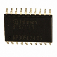
BTS711L1 Infineon Technologies, BTS711L1 Datasheet

BTS711L1
Specifications of BTS711L1
BTS711L1NT
BTS711L1T
BTS711L1XT
BTS711L1XTINTR
BTS711L1XTINTR
SP000011298
SP000379623
Available stocks
Related parts for BTS711L1
BTS711L1 Summary of contents
Page 1
... Smart High-Side Power Switch PROFET BTS711L1 Rev 1.2, 2010-03- ...
Page 2
... On-state resistance R 200 ON Nominal load current , 1.9 / 120 , Current limitation / 6&U P-DSO-20 • AEC qualified • Green product (RoHS compliant) GND1/2 2 GND3/4 6 =150 ) in GND connection, resistor in series with ST GND 2 BTS711L1 43 V bb(AZ) 5.0 ... 34 V bb(on) two parallel four parallel 100 50 m 2.8 4 ...
Page 3
... Block diagram Four Channels; Open Load detection in on state; 9 Data Sheet Smart High-Side Power Switch 3 BTS711L1 Rev 1.2, 2010-03-16 ...
Page 4
... GND and status pins, e.g. with a bb(AZ) 2 (one layer thick) copper area for Smart High-Side Power Switch BTS711L1 Symbol Values self-limited ...
Page 5
... Smart High-Side Power Switch Values min typ max -- 165 200 320 400 83 100 42 50 1.7 1.9 2.6 2.8 4.1 4 200 400 80 200 400 0 0.1 -- off 5 3 5.0 7.0 -- 5.6 7.0 -- 0.2 bb(under 0.5 bb(over OUT bb Rev 1.2, 2010-03-16 BTS711L1 Unit ...
Page 6
... T =-40°C: t j,start off(SC 25°C: j,start 11) V ON(CL > out Smart High-Side Power Switch Values min typ max -- 5.5 9.5 13 4.5 7.5 11 2.5 4.5 twice the current of one channel -- 150 -- -- 610 Rev 1.2, 2010-03-16 BTS711L1 Unit ° ...
Page 7
... V = +1.6 mA: ST ST(high +1.6 mA: ST ST(low) = +1.6 mA Smart High-Side Power Switch Values min typ max 10 -- 200 150 10 -- 150 twice the current of one channel 2.5 3.5 1.7 -- 3.5 1 0.5 -- IN( 100 320 800 -- 200 600 5.4 6 0.4 0 Rev 1.2, 2010-03-16 BTS711L1 Unit ...
Page 8
... H H Channel 1 ( Channel 2 ( Channel 1 ( Channel 2 ( both channel Channel 1 ( Channel 2 ( high impedance, potential depends on external circuit ,R = 150 GND1/2 GND3/4 in the off state causes an internal current from output to ground BTS711L1 OUT2 ST1/2 ST1/2 OUT4 ST3/4 ST3/4 BTS 711L1 BTS 712N1 H(L 16) ...
Page 9
... ON(CL) . Data Sheet Smart High-Side Power Switch Overvoltage protection of logic part IN1...4 GND1/2 or GND3 6.1 V typ 150 GND Reverse battery protection R = 150 GND Temperature protection is not active during inverse current operation. 9 BTS711L1 = 47 V typ 3.5 k typ 3.5 k typ I Rev 1.2, 2010-03-16 ...
Page 10
... Consider at your PCB layout that in the case of Vbb dis- connection with energized inductive load the whole load current flows through the GND connection OUT IN IN(T+) 10 BTS711L1 > device stays off GND IN IN(T+) > low signal available. ST Rev 1.2, 2010-03-16 ...
Page 11
... Maximum allowable load inductance for a single switch off (one channel) T j,start = 150° [mH] Data Sheet Typ. on-state resistance R [mOhm · i (t) dt, ON(CL · ( OUT(CL) Typ. open load detection current 5) I [mA] L(OL [A] 11 Smart High-Side Power Switch BTS711L1 ; high high Rev 1.2, 2010-03- [V] bb ...
Page 12
... Typ. standby current ; V = 9... 1...4 = low bb I [µA] bb(off) Typ. initial short circuit shutdown time ; off - Data Sheet Smart High-Side Power Switch T [° 100 125 150 T [° tart 12 BTS711L1 Rev 1.2, 2010-03-16 ...
Page 13
... Figure 3a: Turn on into short circuit: shut down by overtemperature, restart by cooling Heating up of the chip may require several milliseconds, depending on external conditions (t off(SC) vs. T j,start see page 11) 13 BTS711L1 Rev 1.2, 2010-03-16 ...
Page 14
... OL1) d(ST OL2) Figure 5b: Open load: detection in ON-state, turn on/off to open load IN2 channel 2: normal operation channel 1: open load t The status delay time t allows to distinguish between the d(STOL4) failure modes "open load in ON-state" and "overtemperature". 14 BTS711L1 Rev 1.2, 2010-03-16 ...
Page 15
... OL5) impedance Figure 6a: Undervoltage: V bb(under) Data Sheet Smart High-Side Power Switch Figure 6b: Undervoltage restart of charge pump IN = high, normal load conditions. Charge pump starts at V Figure 7a: Overvoltage: V ON(CL bb(u cp) bb(u rst) 15 BTS711L1 = 5.6 V typ. bb(ucp bb(over) bb(o rst) Rev 1.2, 2010-03-16 ...
Page 16
... Pb-free soldering according to IPC/JEDEC J-STD-020). Please specify the package needed (e.g. green package) when placing an order Data Sheet 0.35 x 45˚ 1) 7.6 -0.2 +0.8 0.4 ±0.3 10.3 0.1 0.2 24x 11 GPS05094 10 1) 12.8 -0.2 16 Smart High-Side Power Switch BTS711L1 Rev 1.2, 2010-03-16 ...
Page 17
... Rev. 1.1 2009-07-21 page 1: added new coverpage page 6: Initial short circuit shutdown time changed: t off(SC) -40 ° off(SC) 25 ° page 12: changed graphic V1.0 2008-04-18 Creation of the Green Data sheet Data Sheet Smart High-Side Power Switch 17 BTS711L1 Rev 1.2, 2010-03-16 ...
Page 18
... Infineon Technologies Office. Infineon Technologies Components may only be used in life-support devices or systems with the express written approval of Infineon Technologies failure of such components can reasonably be expected to cause the failure of that life-support device or system affect the safety or effectiveness of that device or system. Life support devices or systems are intended to be implanted in the human body support and/or maintain and sustain and/or protect human life ...


