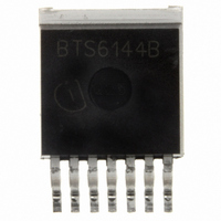
BTS6144B Infineon Technologies, BTS6144B Datasheet

BTS6144B
Specifications of BTS6144B
BTS6144BINTR
BTS6144BNT
BTS6144BT
SP000014073
Available stocks
Related parts for BTS6144B
BTS6144B Summary of contents
Page 1
... Smart SIPMOS chip on chip technology. Providing embedded protective functions. Voltage source Voltage sensor 3 IN ESD Logic GND Infineon Technologies AG PROFET ® Data sheet BTS 6144B/P Product Summary Operating voltage On-state resistance Nominal current Load current (ISO) Current limitation Package TO 220-7-180 Current Gate Overvoltage limit protection protection ...
Page 2
... See also on page 8. Slew rate limitation can be achieved by means of using a series resistor R path. This resistor is also required for reverse operation. See also page 10. Infineon Technologies AG Function Output; output to the load; pin and 7 must be externally shorted* . Input; activates the power switch if shorted to ground. ...
Page 3
... R = 2.2 OUT L 5) Thermal resistance R case to heatsink (about 0.5 ... 0.9 K/W with silicone paste) not included! thCH ) 6 Device on 50mm*50mm*1.5mm epoxy PCB FR4 with 6cm connection. PCB is vertical without blown air. Infineon Technologies AG Symbol R chip - case : thJC thJA ) : 6 Symbol T =25 °C: ...
Page 4
... For operation at voltages higher then |16V| please see required schematic on page 10. 11) Permanent Inverse operation results eventually in a current flow via the intrinsic diode of the power DMOS. In this case the device switches on with a time delay t Infineon Technologies AG Symbol T =-40...150 °C: V ...
Page 5
... Fault conditions are considered as "outside" normal operating range. Protection functions are not designed for continuous repetitive operation. ) Short circuit current limit for max. duration not subject to production test, specified by design 14 ) See also figure 2b on page 12. 15 Infineon Technologies AG 14) =-40° =25°C: ...
Page 6
... Overvoltage protection 16) See also figures 4.x and 6.x on page 13 and 14. 17) Fault conditions are overload during on (i.e. V table on page 8. ) not subject to production test, specified by design 18 Infineon Technologies AG Symbol k ILIS IL = 35A -40° +25° +150° 10A -40° +25° +150° 2.5A -40° +25° ...
Page 7
... Parameter and Conditions 25 unless otherwise specified j bb Input Required current capability of input switch Input current for turn-off Infineon Technologies AG Symbol I IN(on) T =-40..+150° =-40..+150° IN(off) Page Data sheet BTS 6144B/P Values Unit min typ max -- 1.4 2 2003-Oct-01 µA ...
Page 8
... PROFET bIS Two or more devices can easily be connected in parallel to increase load current capability. ) Overload is detected at the following condition: 1V (typ.) < Short Circuit is detected at the following condition Low ohmic short may reduce the output current bb Infineon Technologies AG Input Output Current level level ...
Page 9
... Note: For large values of R the voltage V IS almost V . See also overvoltage protection you don't use the current sense output in your application, you can leave it open. Infineon Technologies AG Inductive and overvoltage output clamp clamped Overvoltage protection of logic part Z, 100 bb nominal ...
Page 10
... The transition from inverse to forward mode can result in a delayed switch on. Note: Temperature protection during inverse load current operation is not possible! Infineon Technologies AG V disconnect with energised inductive bb load Provide a current path with load current capability by ...
Page 11
... L SC [uH 16V 24V bb 15 18V 100 200 Infineon Technologies AG Inductive load switch-off energy dissipation d(SC Energy stored in load inductance: While demagnetizing load inductance, the energy dissipated in PROFET is with an approximate solution for R L OUT ...
Page 12
... I slc(IS) L Load 1 Load son(IS) The sense signal is not valid during a settling time after turn-on/off and after change of load current. Infineon Technologies AG Figure 2a: Switching motors and lamps dV/dtoff OUT off t slc(IS long as V bIS < V Z,IS the sense current will never exceed I IS,fault and/or I IS,lim ...
Page 13
... > L(SC) t d(SC1 IS,fault t delay(fault) Shut down remains latched until next reset via input. Infineon Technologies AG Figure 3c: Short circuit type two: shut down by short circuit detection, reset [V] Shut down remains latched until next reset via input. Figure 4a: Overtemperature Reset ...
Page 14
... L,lim IS,lim IS,fault k ilis Figure 5a: Undervoltage restart of charge pump, overvoltage clamp V OUT V IN dynamic, short Undervoltage not below V bIN( bIN(u) bIN(ucp) Infineon Technologies AG Figure 6a: Current sense versus load current: [mA IS(LH L(MIN) Figure 6b: Current sense ratio k ILIS 30000 = 0 20000 V ON(CL) 10000 ON(CL) V ...
Page 15
... Figure 7a: Output voltage drop versus load current [V] 0.1 V 0.05 ON(NL) 0 Infineon Technologies [ Data sheet BTS 6144B/P 2003-Oct-01 ...
Page 16
... Back side, heatsink contour All metal surfaces tin plated, except area of cut. Infineon Technologies AG Published by Infineon Technologies AG, St.-Martin-Strasse 53, BTS6144B D-81669 München © Infineon Technologies AG 2001 All Rights Reserved. Attention please! The information herein is given to describe certain components and shall not be considered as a guarantee of characteristics ...


