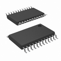
LM96080CIMT/NOPB National Semiconductor, LM96080CIMT/NOPB Datasheet - Page 20

LM96080CIMT/NOPB
Manufacturer Part Number
LM96080CIMT/NOPB
Description
IC HARDWARE MONITOR 24-TSSOP
Manufacturer
National Semiconductor
Series
PowerWise®r
Datasheet
1.LM96080CIMTNOPB.pdf
(30 pages)
Specifications of LM96080CIMT/NOPB
Function
Hardware Monitor
Topology
ADC (Sigma Delta), Comparator, Fan Speed Counter, Register Bank
Sensor Type
External & Internal
Sensing Temperature
-40°C ~ 125°C, External Sensor
Output Type
I²C™
Output Alarm
No
Output Fan
Yes
Voltage - Supply
3 V ~ 5.5 V
Operating Temperature
-40°C ~ 125°C
Mounting Type
Surface Mount
Package / Case
24-TSSOP
Lead Free Status / RoHS Status
Lead free / RoHS Compliant
Other names
LM96080CIM
Available stocks
Company
Part Number
Manufacturer
Quantity
Price
Company:
Part Number:
LM96080CIMT/NOPB
Manufacturer:
National Semiconductor
Quantity:
135
Company:
Part Number:
LM96080CIMT/NOPB
Manufacturer:
NS
Quantity:
175
www.national.com
9.0 THE LM96080 INTERRUPT STRUCTURE
Figure 8
that the number next to each input of the gate represents a
register and bit address. For example, INT_Clear 00h[3]
refers to bit 3, INT_Clear, of register address 00h. The
LM96080 can generate Interrupts as a result of each of its
internal WATCHDOG registers on the analog, temperature,
and fan inputs.
9.1 Interrupt Inputs
External Interrupts can come from the following sources.
While the label suggests a specific type or source of Interrupt,
this label is not a restriction of its usage, and it could come
from any desired source:
•
•
BTI (Board Temperature Interrupt) - This is an active
low Interrupt intended to come from the Overtemperature
Shutdown (O.S.) output of LM75 temperature sensors.
The LM75 O.S. output goes active when its temperature
exceeds a programmed threshold. Up to 8 LM75's can be
connected to a single serial bus with their O.S. output's
wire or'ed to the BTI input of the LM96080. If the
temperature of any LM75 exceeds its programmed limit,
BTI is driven low. This generates an Interrupt via bit 1 of
the Interrupt Status Register 2 (address 02h) to notify the
host of a possible overtemperature condition. To disable
this feature, set bit 1 of the Interrupt Mask Register 2
(address 04h) high. This pin also provides an internal pull-
up resistor of 10 kΩ.
GPI (Chassis Intrusion) - This is an active high interrupt
from any type of device that detects and captures chassis
intrusion violations. This could be accomplished
mechanically, optically, or electrically, and circuitry
external to the LM96080 is expected to latch the event.
Read this Interrupt using bit 4 of the Interrupt Status
Register 2 (address 02h), and disable it using bit 4 of the
Interrupt Mask Register 2 (address 04h). The design of the
LM96080 allows this input to go high even with no power
applied to the LM96080, and no clamping or other
interference with the line will occur. This line can also be
pulled low for at least 10 ms by the LM96080 to reset a
typical Chassis Intrusion circuit. Accomplish this reset by
setting bit 5 of Configuration Register (address 00h) high;
this bit is self-clearing.
depicts the Interrupt Structure of the LM96080. Note
FIGURE 8. Interrupt Structure
20
•
9.2 Interrupt Outputs
All Interrupts are indicated in the two Interrupt Status Regis-
ters.
•
•
9.3 Interrupt Clearing
Reading an Interrupt Status Registers (addresses 01h - 02h)
will output the contents of the Register and reset the Register.
The Interrupt Status Registers clear upon being read. When
the Interrupt Status Registers clear, the INT output pin is also
INT_IN -
chain the INT (Interrupt) from other devices through the
LM96080 to the processor. If this pin is pulled low, then bit
7 of the Interrupt Status Register 1 (address 01h) will go
high indicating this Interrupt detection. Setting bit 1 of the
Configuration Register (address 00h) will also allow the
output INT pin to go low when INT_IN goes low. To disable
this feature, set bit 7 of the Interrupt Mask Register 1
(address 03h) high.
INT - an output pin, not to be confused with the input
INT_IN pin. This pin becomes active whenever INT_IN,
BTI, or GPI interrupts. As described in Section 3.3, INT is
enabled when bit 1 of the Configuration Register (address
00h) is set high. Bits 2 and 3 of the Configuration Register
are also used to set the polarity and state of the INT
Interrupt line.
OS - dedicated to the Temperature reading WATCHDOG.
In the Fan Divisor/RST_OUT/OS Register (address 05h),
the OS enable bit (bit 6), must be set high and the RST
enable bit (bit 7) must be set low to enable the OS function
on the RST_OUT/OS pin. OS pin has two modes of
operation: “One-Time Interrupt” and “Comparator”. “One-
Time Interrupt” mode is selected by taking bit 2 of the
OS Configuration/Temperature Resolution Register
(address 06h) high. If bit 2 is taken low, “Comparator”
mode is selected. Unlike the OS pin, the OS bit in Interrupt
Status Register 2 (address 02h, bit 5) functions in “Default
Interrupt” and “One-Time Interrupt” modes. The OS bit can
be masked to INT pin by taking bit 5 in the Interrupt Mask
Register 2 (address 04h) low. A description of
“Comparator”, “Default Interrupt”, and “One-Time
Interrupt” modes can be found in Section 8.1.
This active low Interrupt provides a way to
30070118


