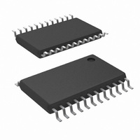
LM80CIMT-5/NOPB National Semiconductor, LM80CIMT-5/NOPB Datasheet - Page 7

LM80CIMT-5/NOPB
Manufacturer Part Number
LM80CIMT-5/NOPB
Description
IC MONITOR SYS HARDWAR 24-TSSOP
Manufacturer
National Semiconductor
Series
PowerWise®r
Datasheet
1.LM80CIMT-3NOPB.pdf
(30 pages)
Specifications of LM80CIMT-5/NOPB
Function
Hardware Monitor
Topology
ADC, Comparator, Fan Speed Counter, Register Bank
Sensor Type
External & Internal
Sensing Temperature
-25°C ~ 125°C, External Sensor
Output Type
I²C™
Output Alarm
No
Output Fan
No
Voltage - Supply
2.8 V ~ 5.75 V
Operating Temperature
-25°C ~ 125°C
Mounting Type
Surface Mount
Package / Case
24-TSSOP
Manual Reset
Not Resettable
Watchdog
Watchdog
Battery Backup Switching
No
Supply Voltage (max)
5.75 V
Supply Voltage (min)
2.8 V
Supply Current (typ)
200 uA (Typ)
Maximum Operating Temperature
+ 125 C
Minimum Operating Temperature
- 25 C
Power Fail Detection
No
Ic Output Type
Digital
Sensing Accuracy Range
± 3°C
Supply Current
200µA
Supply Voltage Range
2.8V To 5.75V
Sensor Case Style
TSSOP
No. Of Pins
24
Filter Terminals
Solder
Rohs Compliant
Yes
Accuracy %
3°C
For Use With
LM80EVAL - EVALUATION BOARD FOR LM80
Lead Free Status / RoHS Status
Lead free / RoHS Compliant
Other names
*LM80CIMT-5
*LM80CIMT-5/NOPB
LM80CIMT-5
*LM80CIMT-5/NOPB
LM80CIMT-5
Available stocks
Company
Part Number
Manufacturer
Quantity
Price
Company:
Part Number:
LM80CIMT-5/NOPB
Manufacturer:
NS
Quantity:
3 843
Company:
Part Number:
LM80CIMT-5/NOPB
Manufacturer:
NS/TI
Quantity:
3 500
Note 8: Typicals are at T
Note 9: Limits are guaranteed to National's AOQL (Average Outgoing Quality Level).
Note 10: TUE (Total Unadjusted Error) includes Offset, Gain and Linearity errors of the ADC.
Note 11: Total Monitoring Cycle Time includes temperature conversion, 7 analog input voltage conversions and 2 tachometer readings. Each input voltage
conversion takes 100 ms typical and 112 ms maximum. 8-plus sign Temperature resolution takes 100 ms typical and 112 ms maximum, while 11-bit plus sign
takes 800 ms typical and 900 ms maximum. Fan tachometer readings take 20 ms typical, at 4400 rpm, and 200 ms max.
Note 12: The total fan count is based on 2 pulses per revolution of the fan tachometer output.
Note 13: Timing specifications are tested at the Serial Bus Input logic levels, V
SCL and SDA edge rates are similar.
Test Circuit
INT_IN
CI
GPO
FAN1–FAN2
SCL
SDA
RST_OUT/OS
J
=T
A
Pin Name
=25°C and represent most likely parametric norm.
D1
FIGURE 3. Digital Output Load Test Circuitry
x
FIGURE 2. ESD Protection Input Structure
D2
x
x
x
x
x
D3
x
x
x
x
x
x
IN(0)
7
= 0.3 × V
NTEST_IN/
Reset_IN
IN0-IN6
BTI
INT
A1-A2
A0/NTEST_Out
+
for a falling edge and V
Pin Name
IN(1)
D1
x
x
x
x
x
=0.7 × V
D2
10004006
x
x
x
x
x
+
D3
for a rising edge, when the
x
x
x
x
x
x
www.national.com


