LM2984T/NOPB National Semiconductor, LM2984T/NOPB Datasheet - Page 15
LM2984T/NOPB
Manufacturer Part Number
LM2984T/NOPB
Description
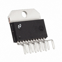
IC CONV MICROPROCESSOR TO220-11
Manufacturer
National Semiconductor
Datasheet
1.LM2984TNOPB.pdf
(20 pages)
Specifications of LM2984T/NOPB
Applications
Converter, Microprocessor
Voltage - Input
6 ~ 26 V
Number Of Outputs
3
Voltage - Output
5V
Operating Temperature
-40°C ~ 125°C
Mounting Type
Through Hole
Package / Case
TO-220-11 (Bent and Staggered Leads)
Lead Free Status / RoHS Status
Contains lead / RoHS non-compliant
Other names
*LM2984T
*LM2984T/NOPB
LM2984T
*LM2984T/NOPB
LM2984T


Application Hints
OUTPUT CAPACITORS
The LM2984 output capacitors are required for stability. With-
out them, the regulator outputs will oscillate, sometimes by
many volts. Though the 10 μF shown are the minimum rec-
ommended values, actual size and type may vary depending
upon the application load and temperature range. Capacitor
effective series resistance (ESR) also affects the IC stability.
Since ESR varies from one brand to the next, some bench
work may be required to determine the minimum capacitor
value to use in production. Worst case is usually determined
at the minimum ambient temperature and the maximum load
expected.
Output capacitors can be increased in size to any desired
value above the minimum. One possible purpose of this would
be to maintain the output voltages during brief conditions of
negative input transients that might be characteristic of a par-
ticular system.
Capacitors must also be rated at all ambient temperatures
expected in the system. Many aluminum type electrolytics will
freeze at temperatures less than −30°C, reducing their effec-
tive capacitance to zero. To maintain regulator stability down
to −40°C, capacitors rated at that temperature (such as tan-
talums) must be used.
Each output must be terminated by a capacitor, even if it is
not used.
STANDBY OUTPUT
The standby output is intended for use in systems requiring
standby memory circuits. While the high current regulator
outputs are controlled with the ON/OFF pin described later,
the standby output remains on under all conditions as long as
sufficient input voltage is supplied to the IC. Thus, memory
and other circuits powered by this output remain unaffected
by positive line transients, thermal shutdown, etc.
The standby regulator circuit is designed so that the quiescent
current to the IC is very low (<1.5 mA) when the other regu-
lator outputs are off.
The capacitor on the output of this regulator can be increased
without bound. This will help maintain the output voltage dur-
ing negative input transients and will also help to reduce the
noise on all three outputs. Because the other two track the
standby output: therefore any noise reduction here will also
reduce the other two noise voltages.
BUFFER OUTPUT
The buffer output is designed to drive peripheral sensor cir-
cuitry in a μP system. It will track the standby and main
regulator within a few millivolts in normal operation. There-
fore, a peripheral sensor can be powered off this supply and
have the same operating voltage as the μP system. This is
important if a ratiometric sensor system is being used.
The buffer output can be short circuited while the other two
outputs are in normal operation. This protects the μP system
from disruption of power when a sensor wire, etc. is tem-
porarily shorted to ground, i.e. only the sensor signal would
be interrupted, while the μP and memory circuits would re-
main operational.
The buffer output is similar to the main output in that it is con-
trolled by the ON/OFF switch in order to save power in the
standby mode. It is also fault protected against overvoltage
and thermal overload. If the input voltage rises above approx-
imately 30V (e.g. load dump), this output will automatically
shut down. This protects the internal circuitry and enables the
15
IC to survive higher voltage transients than would otherwise
be expected. Thermal shutdown is necessary since this out-
put is one of the dominant sources of power dissipation in the
IC.
MAIN OUTPUT
The main output is designed to power relatively large loads,
i.e. approximately 500 mA. It is therefore also protected
against overvoltage and thermal overload.
This output will track the other two within a few millivolts in
normal operation. It can therefore be used as a reference
voltage for any signal derived from circuitry powered off the
standby or buffer outputs. This is important in a ratiometric
sensor system or any system requiring accurate matching of
power supply voltages.
ON/OFF SWITCH
The ON/OFF switch controls the main output and the buffer
output. The threshold voltage is compatible with most logic
families and has about 20 mV of hysteresis to insure “clean”
switching from the standby mode to the active mode and vice
versa. This pin can be tied to the input voltage through a
10 kΩ resistor if the regulator is to be powered continuously.
POWER DOWN OVERRIDE
Another possible approach is to use a diode in series with the
ON/OFF signal and another in series with the main output in
order to maintain power for some period of time after the ON/
OFF signal has been removed (see Figure 1). When the ON/
OFF switch is initially pulled high through diode D1, the main
output will turn on and supply power through diode D2 to the
ON/OFF switch effectively latching the main output. An open
collector transistor Q1 is connected to the ON/OFF pin along
with the two diodes and forces the regulators off after a period
of time determined by the μP. In this way, the μP can override
a power down command and store data, do housekeeping,
etc. before reverting back to the standby mode.
RESET OUTPUT
This output is an open collector NPN transistor which is forced
low whenever an error condition is present at the main output
or when a μP error is sensed (see μP Monitor section). If the
main output voltage drops by 350 mV or rises out of regulation
by 600 mV typically, the RESET output is forced low and held
low for a period of time set by two external components, R
and C
threshold voltages so that the RESET output has a fast rise
and fall time compatible with the requirements of most μP
RESET inputs.
DELAYED RESET
Resistor R
RESET output is held low after a main output error condition
has been sensed. The delay is given by the formula:
t
. There is a slight amount of hysteresis in these two
t
and capacitor C
FIGURE 1. Power Down Override
t
set the period of time that the
www.national.com
1125213
t
Related parts for LM2984T/NOPB
Image
Part Number
Description
Manufacturer
Datasheet
Request
R

Part Number:
Description:
IC,VOLT REGULATOR,FIXED,+5V,BIPOLAR,ZIP,11PIN,PLASTIC
Manufacturer:
National Semiconductor
Datasheet:
Part Number:
Description:
National Semiconductor [8-Bit D/A Converter]
Manufacturer:
National Semiconductor
Datasheet:
Part Number:
Description:
National Semiconductor [Media Coprocessor]
Manufacturer:
National Semiconductor
Datasheet:
Part Number:
Description:
Digitally Controlled Tone and Volume Circuit with Stereo Audio Power Amplifier, Microphone Preamp Stage and National 3D Sound
Manufacturer:
National Semiconductor
Datasheet:
Part Number:
Description:
Digitally Controlled Tone and Volume Circuit with Stereo Audio Power Amplifier, Microphone Preamp Stage and National 3D Sound
Manufacturer:
National Semiconductor
Datasheet:
Part Number:
Description:
AC97 Rev 2 Codec with Sample Rate Conversion and National 3D Sound
Manufacturer:
National Semiconductor
Part Number:
Description:
Manufacturer:
National Semiconductor
Datasheet:
Part Number:
Description:
Manufacturer:
National Semiconductor
Datasheet:
Part Number:
Description:
General Purpose, Low Voltage, Low Power, Rail-to-Rail Output Operational Amplifiers
Manufacturer:
National Semiconductor
Datasheet:
Part Number:
Description:
8-bit 20 MSPS flash A/D converter.
Manufacturer:
National Semiconductor
Datasheet:
Part Number:
Description:
Low Noise Quad Operational Amplifier
Manufacturer:
National Semiconductor
Datasheet:
Part Number:
Description:
Quad Differential Line Receivers
Manufacturer:
National Semiconductor
Datasheet:
Part Number:
Description:
Quad High Speed Trapezoidal? Bus Transceiver
Manufacturer:
National Semiconductor
Datasheet:
Part Number:
Description:
Dual Line Receiver
Manufacturer:
National Semiconductor
Datasheet: